
How to Use 38mm 8x8 dot matrix row cathode led display: Examples, Pinouts, and Specs
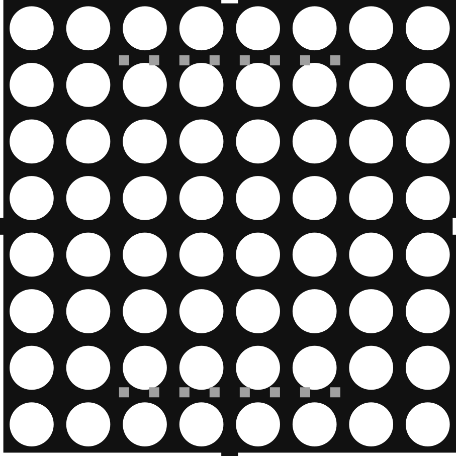
 Design with 38mm 8x8 dot matrix row cathode led display in Cirkit Designer
Introduction
The 38mm 8x8 Dot Matrix Row Cathode LED Display is a compact and versatile LED display module featuring an 8x8 grid of light-emitting diodes. This component is designed for visual output of characters, symbols, and simple animations. Its row cathode configuration simplifies the control of individual rows, making it an excellent choice for applications requiring dynamic visual displays.
Explore Projects Built with 38mm 8x8 dot matrix row cathode led display
 Open Project in Cirkit Designer
 Open Project in Cirkit Designer
 Open Project in Cirkit Designer
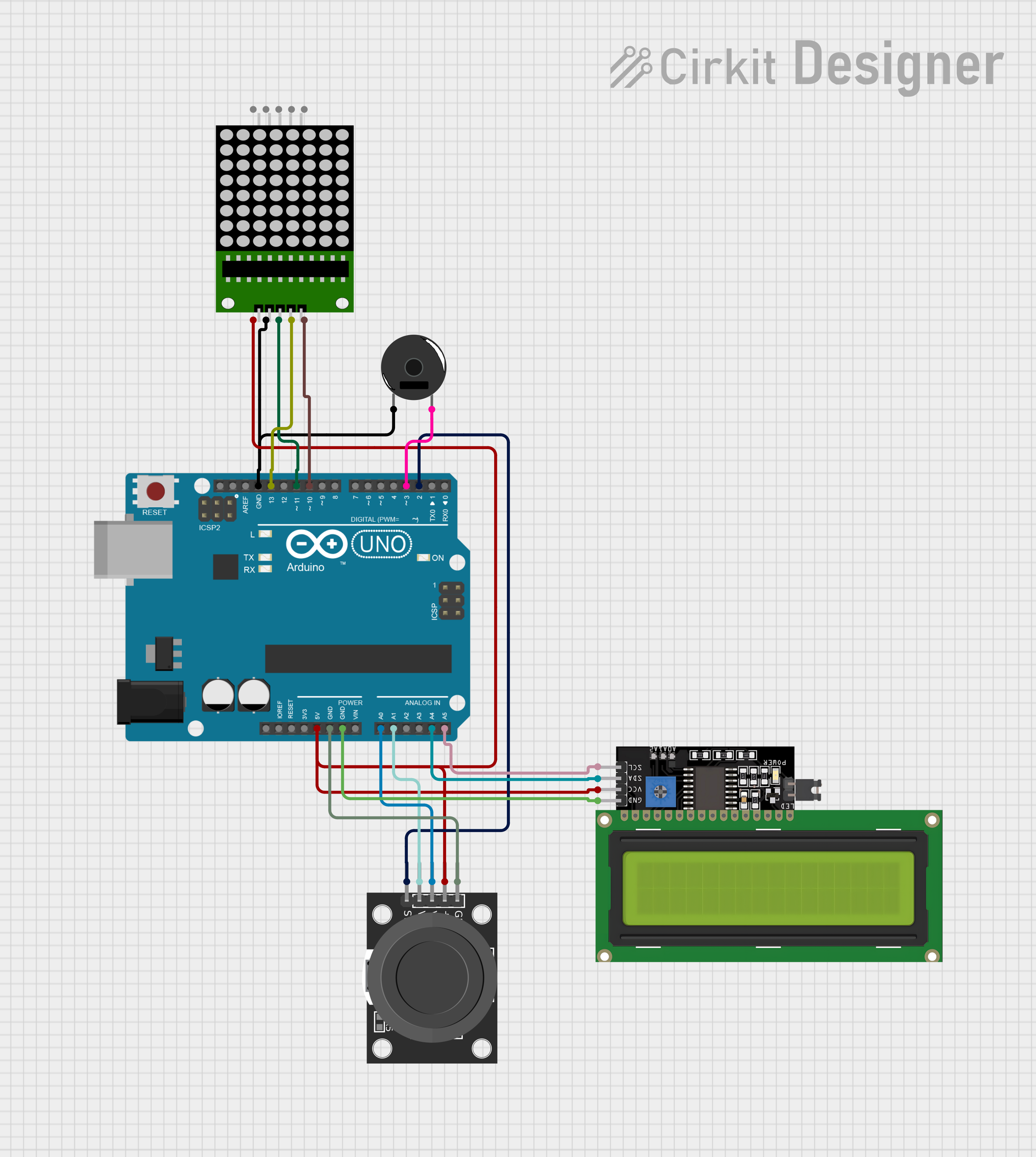 Open Project in Cirkit Designer
Explore Projects Built with 38mm 8x8 dot matrix row cathode led display
Open Project in Cirkit DesignerOpen Project in Cirkit DesignerOpen Project in Cirkit DesignerOpen Project in Cirkit DesignerCommon Applications
- Digital signage and message boards
- Scoreboards and counters
- Simple animations and visual effects
- Educational projects and prototyping
- Arduino-based projects for text or symbol display
Technical Specifications
Below are the key technical details of the 38mm 8x8 Dot Matrix Row Cathode LED Display:
| Parameter | Value |
|---|---|
| LED Configuration | 8x8 grid (64 LEDs total) |
| Dimensions | 38mm x 38mm |
| LED Color | Red (or other variants) |
| Forward Voltage (per LED) | 1.8V to 2.2V |
| Forward Current (per LED) | 10mA to 20mA |
| Max Power Consumption | ~1.4W (all LEDs on) |
| Row Configuration | Cathode |
| Operating Temperature | -40°C to +85°C |
Pin Configuration
The display has 16 pins, with 8 pins controlling the rows (cathodes) and 8 pins controlling the columns (anodes). Below is the pinout description:
| Pin Number | Function | Description |
|---|---|---|
| 1-8 | Row Cathodes (R1-R8) | Controls the cathodes for rows 1 to 8 |
| 9-16 | Column Anodes (C1-C8) | Controls the anodes for columns 1 to 8 |
Note: The exact pin numbering may vary depending on the manufacturer. Always refer to the datasheet for your specific module.
Usage Instructions
How to Use the Component in a Circuit
- Power Requirements: Ensure the display is powered with a suitable voltage (typically 5V for most circuits). Use current-limiting resistors (220Ω to 330Ω) to protect the LEDs.
- Multiplexing: Since the display has 64 LEDs but only 16 pins, it requires multiplexing to control individual LEDs. This involves activating one row at a time while setting the appropriate column states.
- Driver ICs: Use a driver IC like the MAX7219 or 74HC595 shift registers to simplify control. These ICs reduce the number of microcontroller pins required and handle multiplexing internally.
- Microcontroller: Connect the display to a microcontroller (e.g., Arduino UNO) for dynamic control of the LEDs.
Example Circuit
- Connect the row cathodes (R1-R8) to the driver IC or microcontroller through current-limiting resistors.
- Connect the column anodes (C1-C8) directly to the driver IC or microcontroller.
- Ensure proper grounding and power supply connections.
Arduino UNO Example Code
Below is an example code to display a simple pattern on the 8x8 dot matrix using an Arduino UNO and a MAX7219 driver IC:
#include <LedControl.h>
// Include the LedControl library for MAX7219 control

// Pin connections to MAX7219: DIN, CLK, CS
LedControl lc = LedControl(12, 11, 10, 1);
// DIN to pin 12, CLK to pin 11, CS to pin 10

void setup() {
  lc.shutdown(0, false); // Wake up the MAX7219
  lc.setIntensity(0, 8); // Set brightness level (0-15)
  lc.clearDisplay(0);    // Clear the display
  displayPattern();      // Call function to display a pattern
}

void loop() {
  // Main loop can be used for dynamic updates
}

void displayPattern() {
  // Define a simple pattern (e.g., a smiley face)
  byte pattern[8] = {
    B00111100, // Row 1
    B01000010, // Row 2
    B10100101, // Row 3
    B10000001, // Row 4
    B10100101, // Row 5
    B10011001, // Row 6
    B01000010, // Row 7
    B00111100  // Row 8
  };

  // Send the pattern to the display
  for (int row = 0; row < 8; row++) {
    lc.setRow(0, row, pattern[row]);
    // Set each row of the display
  }
}
Note: The
LedControllibrary must be installed in your Arduino IDE. You can install it via the Library Manager.
Best Practices
- Always use current-limiting resistors to prevent damage to the LEDs.
- Avoid driving the display directly from microcontroller pins without a driver IC.
- Use decoupling capacitors near the power pins of the driver IC to reduce noise.
Troubleshooting and FAQs
Common Issues
No LEDs Light Up
- Check power and ground connections.
- Verify that the driver IC or microcontroller is properly connected and programmed.
Dim or Flickering LEDs
- Ensure the current-limiting resistors are of the correct value.
- Check for loose connections or insufficient power supply.
Incorrect Pattern Displayed
- Verify the pin connections between the display and the driver IC/microcontroller.
- Double-check the code for errors in row/column addressing.
FAQs
Q: Can I control the display without a driver IC?
A: Yes, but it requires more microcontroller pins and manual multiplexing in your code, which can be complex and inefficient.
Q: How do I increase the brightness of the LEDs?
A: You can increase the brightness by reducing the value of the current-limiting resistors, but ensure the current does not exceed the LED's maximum rating.
Q: Can I daisy-chain multiple displays?
A: Yes, if using a driver IC like the MAX7219, you can daisy-chain multiple displays for larger matrices.
By following this documentation, you can effectively integrate the 38mm 8x8 Dot Matrix Row Cathode LED Display into your projects for dynamic and engaging visual outputs.