How to Use 3.3V regulator: Examples, Pinouts, and Specs
Introduction
The AMS1117 3.3 is a low dropout (LDO) voltage regulator manufactured by Advanced Monolithic Systems. It is designed to provide a stable 3.3V output voltage from a higher input voltage, making it ideal for powering electronic circuits and components that require a constant 3.3V supply. With its compact design and ease of use, the AMS1117 3.3 is widely used in various applications, including microcontroller-based projects, sensors, and communication modules.
Explore Projects Built with 3.3V regulator


Explore Projects Built with 3.3V regulator
Common Applications and Use Cases
- Powering microcontrollers such as Arduino, ESP8266, and ESP32.
- Supplying stable voltage to sensors and modules (e.g., GPS, Bluetooth, Wi-Fi).
- Voltage regulation in battery-powered devices.
- General-purpose voltage regulation in embedded systems.
Technical Specifications
The AMS1117 3.3 is a versatile and reliable voltage regulator with the following key specifications:
| Parameter | Value |
|---|---|
| Output Voltage | 3.3V ± 1% |
| Input Voltage Range | 4.5V to 15V |
| Maximum Output Current | 1A |
| Dropout Voltage | 1.1V at 1A load |
| Quiescent Current | 5mA (typical) |
| Operating Temperature | -40°C to +125°C |
| Package Types | SOT-223, TO-252, and others |
Pin Configuration and Descriptions
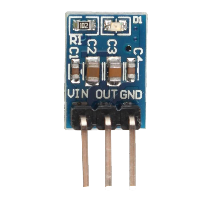
The AMS1117 3.3 typically comes in a 3-pin SOT-223 package. The pinout is as follows:
| Pin Number | Pin Name | Description |
|---|---|---|
| 1 | VIN | Input voltage (4.5V to 15V). Connect to the power source. |
| 2 | GND | Ground. Connect to the circuit ground. |
| 3 | VOUT | Regulated 3.3V output. Connect to the load. |
Usage Instructions
How to Use the AMS1117 3.3 in a Circuit
- Input Voltage: Ensure the input voltage (VIN) is at least 4.5V and no more than 15V. For optimal performance, the input voltage should be at least 1.1V higher than the desired output voltage (i.e., >4.4V for a 3.3V output).
- Capacitors: Use external capacitors for stability:
- Connect a 10µF capacitor between VIN and GND.
- Connect a 10µF capacitor between VOUT and GND.
- Use low ESR capacitors (e.g., tantalum or ceramic) for best results.
- Connections:
- Connect the VIN pin to the input voltage source.
- Connect the GND pin to the circuit ground.
- Connect the VOUT pin to the load requiring 3.3V.
Important Considerations and Best Practices
- Heat Dissipation: The AMS1117 3.3 can dissipate heat during operation, especially at high input voltages and output currents. Use a heatsink or ensure proper ventilation if the regulator gets too hot.
- Current Limitation: Do not exceed the maximum output current of 1A to avoid damaging the regulator.
- Bypass Capacitors: Place the input and output capacitors as close to the regulator pins as possible to minimize noise and improve stability.
Example: Using AMS1117 3.3 with Arduino UNO
The AMS1117 3.3 can be used to power 3.3V sensors or modules in an Arduino project. Below is an example circuit and code to interface a 3.3V sensor with an Arduino UNO:
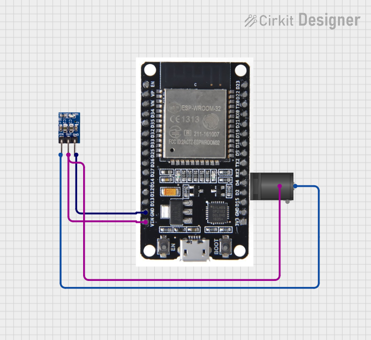
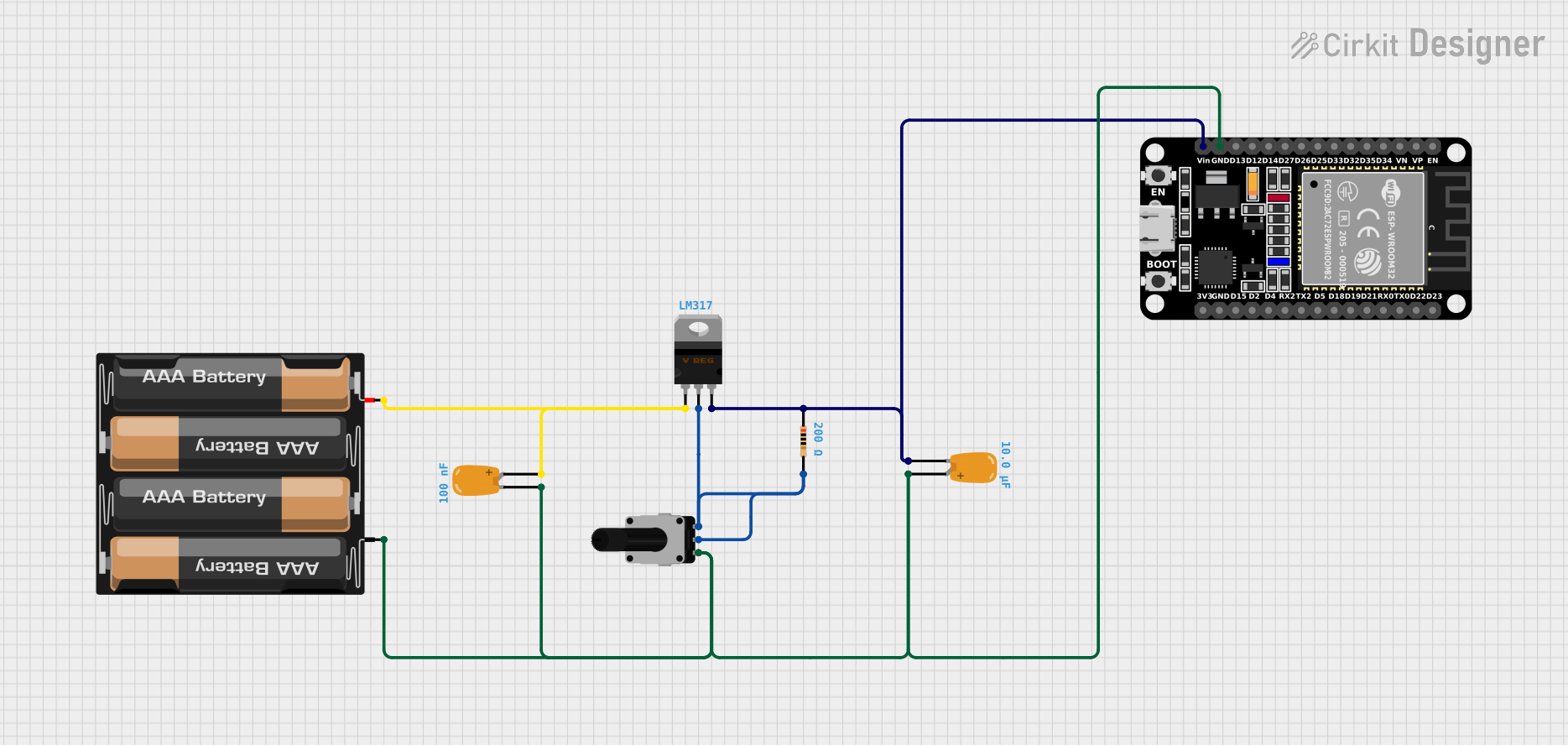
Circuit Diagram
- Connect the AMS1117 3.3 as described above.
- Use the VOUT pin to power the 3.3V sensor.
- Connect the sensor's data pin to an appropriate Arduino pin.
Example Code
// Example code to read data from a 3.3V sensor using Arduino UNO
// Ensure the sensor is powered by the AMS1117 3.3 regulator

const int sensorPin = A0; // Analog pin connected to the sensor output
int sensorValue = 0;      // Variable to store the sensor reading

void setup() {
  Serial.begin(9600); // Initialize serial communication
  pinMode(sensorPin, INPUT); // Set the sensor pin as input
}

void loop() {
  // Read the sensor value
  sensorValue = analogRead(sensorPin);

  // Print the sensor value to the Serial Monitor
  Serial.print("Sensor Value: ");
  Serial.println(sensorValue);

  delay(1000); // Wait for 1 second before the next reading
}
Troubleshooting and FAQs
Common Issues and Solutions
No Output Voltage:
- Check the input voltage. Ensure it is within the specified range (4.5V to 15V).
- Verify the connections, especially the GND pin.
- Ensure the input and output capacitors are properly connected.
Overheating:
- Reduce the input voltage if possible.
- Ensure the load current does not exceed 1A.
- Use a heatsink or improve ventilation around the regulator.
Unstable Output Voltage:
- Check the capacitors. Use low ESR capacitors and place them close to the regulator pins.
- Verify that the input voltage is stable and free from noise.
FAQs
Q: Can I use the AMS1117 3.3 to power a 3.3V microcontroller directly?
A: Yes, the AMS1117 3.3 is suitable for powering 3.3V microcontrollers, provided the input voltage is within the specified range and the current requirements do not exceed 1A.
Q: What happens if the input voltage drops below 4.5V?
A: If the input voltage is too low, the regulator may fail to maintain a stable 3.3V output, leading to erratic behavior in the connected circuit.
Q: Can I use the AMS1117 3.3 without capacitors?
A: No, external capacitors are essential for stable operation. Omitting them may result in unstable output voltage and poor performance.
Q: Is the AMS1117 3.3 suitable for battery-powered applications?
A: Yes, but ensure the battery voltage is within the input range and consider the dropout voltage when designing the circuit.