
Cirkit Designer
Your all-in-one circuit design IDE
Home /
Component Documentation
How to Use Placa 2: Examples, Pinouts, and Specs
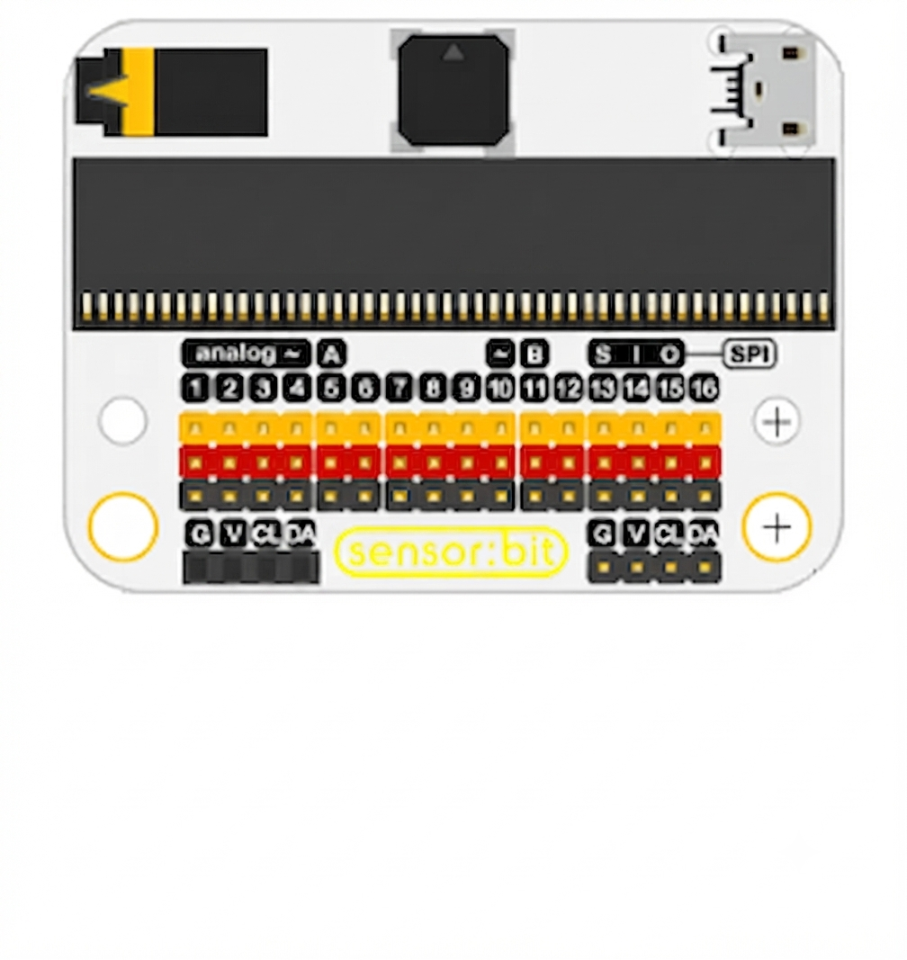
 Design with Placa 2 in Cirkit Designer
Introduction
Placa 2, manufactured by Arduino with the part ID "UNO," is a versatile printed circuit board (PCB) designed for mounting electronic components and establishing electrical connections between them. It serves as a foundational platform for prototyping, testing, and deploying electronic circuits. Placa 2 is widely used in educational, hobbyist, and professional projects due to its reliability and ease of use.
Explore Projects Built with Placa 2
ESP32-Based Wi-Fi Controlled Robotic Car with OLED Display and Laser Shooting
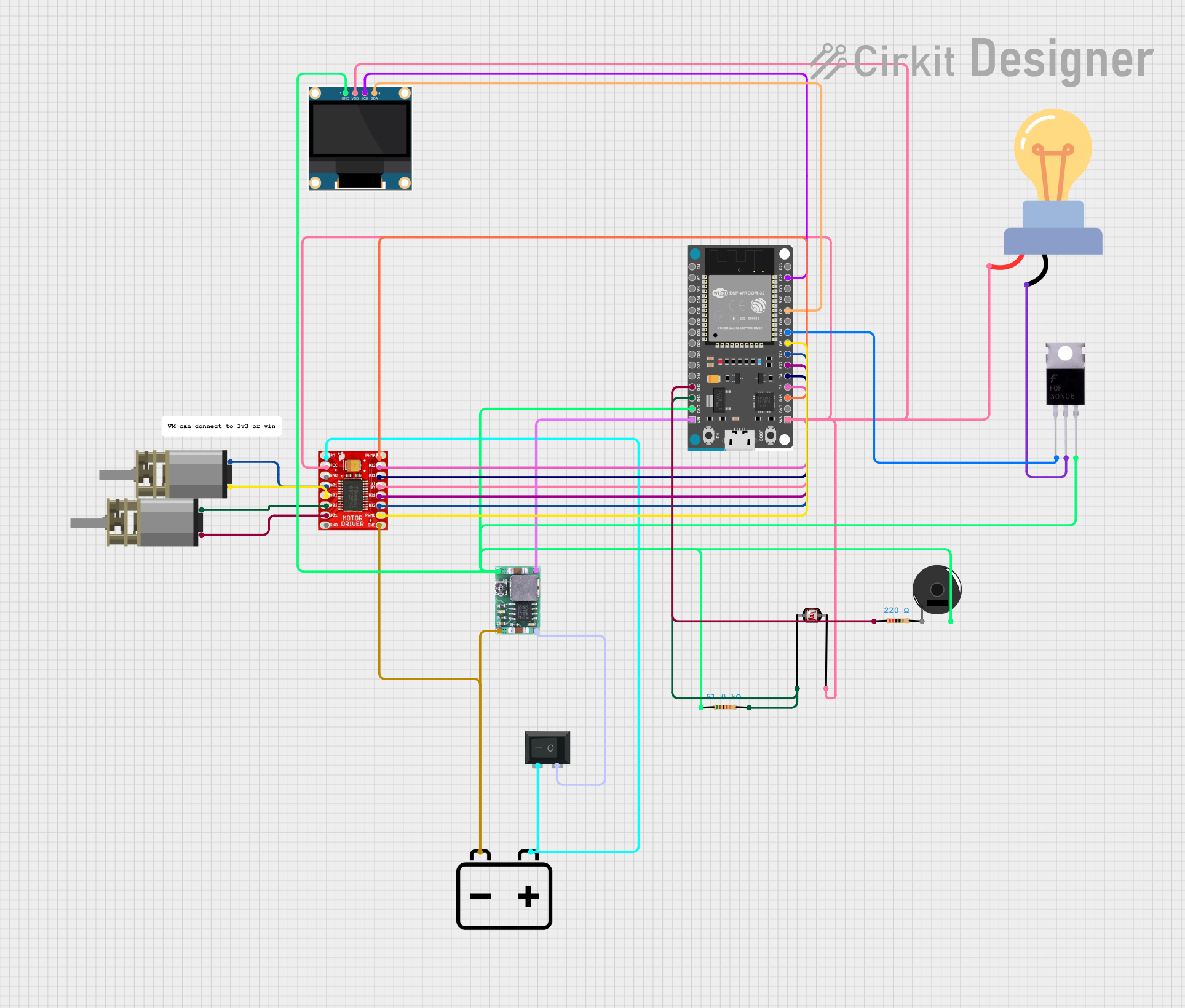
This circuit is a remote-controlled shooting game system using an ESP32 microcontroller, which interfaces with a PS3 controller to control two DC motors via a TB6612FNG motor driver, and a laser for shooting. The system includes an OLED display for game status, a photocell for detecting laser hits, and a piezo buzzer for sound feedback.
Open Project in Cirkit DesignerESP32-Based Wi-Fi Controlled Laser Shooting Game with OLED Display
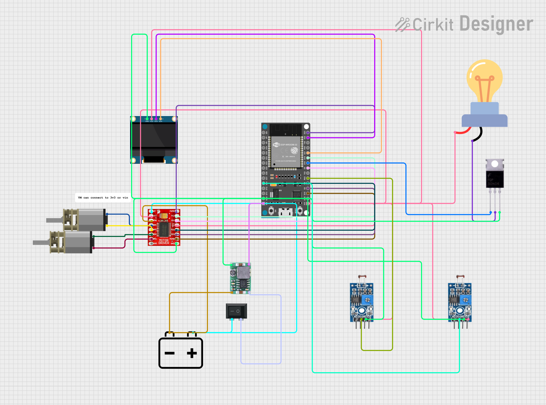
This circuit is a laser shooting game controlled by a PS3 controller, featuring an ESP32 microcontroller, two photosensitive sensors for light detection, and a motor driver to control two DC motors. The game includes an OLED display for score visualization, and a MOSFET to control an LED bulb, with power supplied by a 12V battery and regulated by a DC-DC step-down converter.
Open Project in Cirkit DesignerRaspberry Pi Pico-based PS2 Controller Emulator with ADS1115 Analog Input
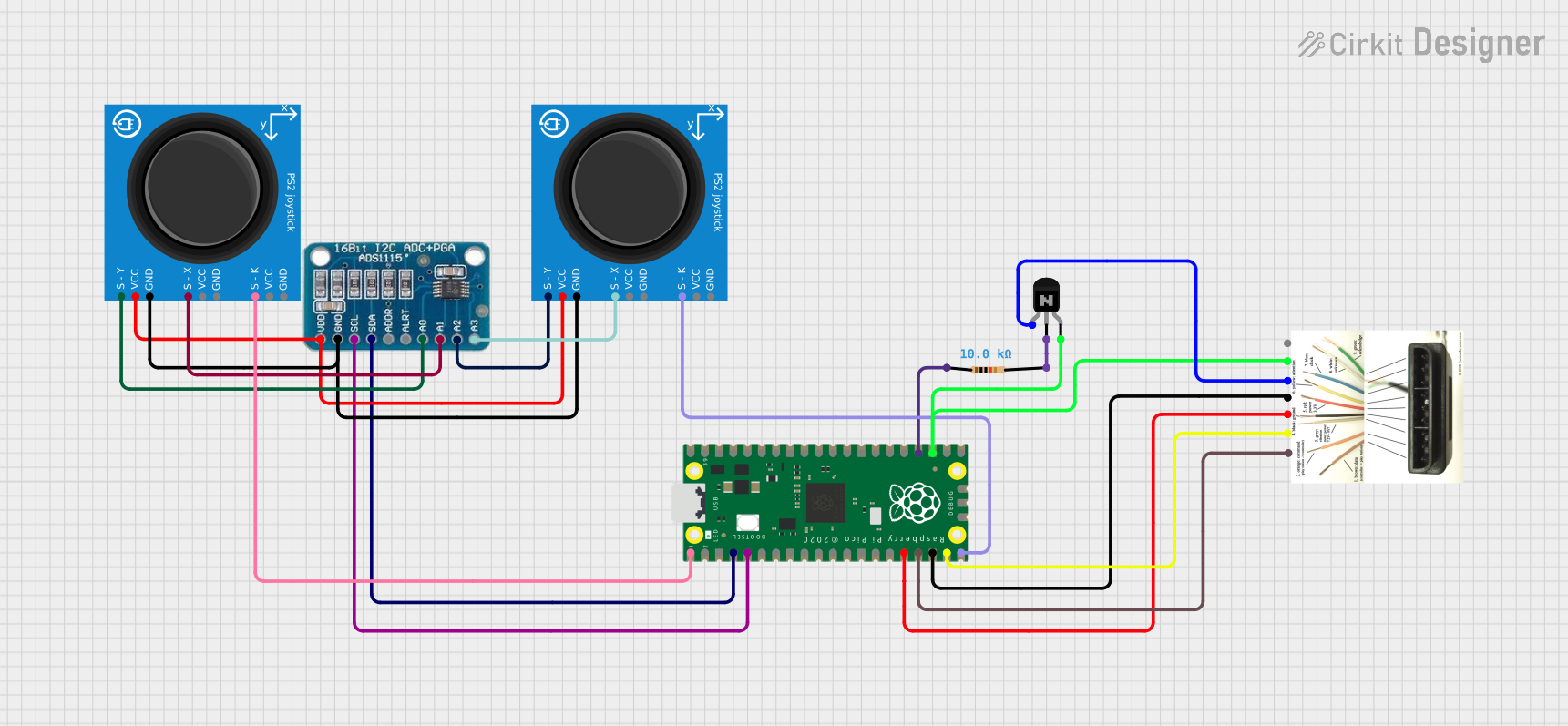
This circuit appears to be a game controller interface that uses a Raspberry Pi Pico microcontroller to emulate a PS2 controller, interfacing with a PS2 joystick and a PS2 console cable. The ADS1115 analog-to-digital converter is used to read the joystick's analog signals, and the microcontroller's SPI and I2C interfaces are utilized for communication with the PS2 console and the ADS1115, respectively. Additionally, an NPN transistor and a resistor are configured to handle the PS2 controller's acknowledge signal.
Open Project in Cirkit DesignerESP32-Controlled Automated Transport System with OLED Display and Stepper Motor

This circuit is designed for interactive control of a stepper motor using a PS2 joystick, with an ESP32 microcontroller at its core. It features visual feedback through an OLED display and LED indicators, and includes a buzzer for audio alerts. The system likely serves an automation or robotics application, with the ESP32 handling input processing, motor control, and user interface updates.
Open Project in Cirkit DesignerExplore Projects Built with Placa 2
ESP32-Based Wi-Fi Controlled Robotic Car with OLED Display and Laser Shooting
This circuit is a remote-controlled shooting game system using an ESP32 microcontroller, which interfaces with a PS3 controller to control two DC motors via a TB6612FNG motor driver, and a laser for shooting. The system includes an OLED display for game status, a photocell for detecting laser hits, and a piezo buzzer for sound feedback.
Open Project in Cirkit DesignerESP32-Based Wi-Fi Controlled Laser Shooting Game with OLED Display
This circuit is a laser shooting game controlled by a PS3 controller, featuring an ESP32 microcontroller, two photosensitive sensors for light detection, and a motor driver to control two DC motors. The game includes an OLED display for score visualization, and a MOSFET to control an LED bulb, with power supplied by a 12V battery and regulated by a DC-DC step-down converter.
Open Project in Cirkit DesignerRaspberry Pi Pico-based PS2 Controller Emulator with ADS1115 Analog Input
This circuit appears to be a game controller interface that uses a Raspberry Pi Pico microcontroller to emulate a PS2 controller, interfacing with a PS2 joystick and a PS2 console cable. The ADS1115 analog-to-digital converter is used to read the joystick's analog signals, and the microcontroller's SPI and I2C interfaces are utilized for communication with the PS2 console and the ADS1115, respectively. Additionally, an NPN transistor and a resistor are configured to handle the PS2 controller's acknowledge signal.
Open Project in Cirkit DesignerESP32-Controlled Automated Transport System with OLED Display and Stepper Motor
This circuit is designed for interactive control of a stepper motor using a PS2 joystick, with an ESP32 microcontroller at its core. It features visual feedback through an OLED display and LED indicators, and includes a buzzer for audio alerts. The system likely serves an automation or robotics application, with the ESP32 handling input processing, motor control, and user interface updates.
Open Project in Cirkit DesignerCommon Applications and Use Cases
- Prototyping and testing electronic circuits
- Educational projects for learning electronics and programming
- IoT (Internet of Things) applications
- Robotics and automation systems
- Signal processing and sensor interfacing
Technical Specifications
Key Technical Details
| Parameter | Specification |
|---|---|
| Manufacturer | Arduino |
| Part ID | UNO |
| PCB Type | Single-layer or multi-layer PCB |
| Material | FR4 (Flame Retardant 4) |
| Dimensions | 68.6 mm x 53.4 mm |
| Operating Voltage | 5V |
| Input Voltage (recommended) | 7-12V |
| Input Voltage (limit) | 6-20V |
| Digital I/O Pins | 14 (6 PWM outputs) |
| Analog Input Pins | 6 |
| DC Current per I/O Pin | 20 mA |
| Flash Memory | 32 KB (0.5 KB used by bootloader) |
| SRAM | 2 KB |
| EEPROM | 1 KB |
| Clock Speed | 16 MHz |
Pin Configuration and Descriptions
| Pin Number | Pin Name | Description |
|---|---|---|
| 1-14 | Digital Pins | General-purpose digital I/O pins. Pins 3, 5, 6, 9, 10, and 11 support PWM. |
| A0-A5 | Analog Pins | Analog input pins for reading sensor data (0-5V range). |
| VIN | Voltage Input | External power supply input (7-12V recommended). |
| GND | Ground | Ground connection for the circuit. |
| 5V | 5V Output | Regulated 5V output for powering external components. |
| 3.3V | 3.3V Output | Regulated 3.3V output for low-power components. |
| RESET | Reset Pin | Resets the microcontroller when pulled LOW. |
Usage Instructions
How to Use the Component in a Circuit
- Powering the Board: Connect an external power source to the VIN pin (7-12V recommended) or use the USB port for power and programming.
- Connecting Components: Use the digital and analog pins to interface with sensors, actuators, and other peripherals.
- Programming: Use the Arduino IDE to write and upload code to the board via the USB connection.
- Grounding: Ensure all components share a common ground (GND) to avoid electrical issues.
Important Considerations and Best Practices
- Voltage Levels: Avoid exceeding the maximum voltage ratings (20V for VIN, 5V for I/O pins) to prevent damage.
- Current Limits: Ensure connected components do not draw more than 20 mA per I/O pin or exceed the total current capacity of the board.
- Heat Management: If using high-power components, consider adding heat sinks or cooling mechanisms to prevent overheating.
- Static Protection: Handle the board with care to avoid static discharge, which can damage sensitive components.
Example Code for Arduino UNO
Below is an example code snippet to blink an LED connected to digital pin 13:
// This code blinks an LED connected to pin 13 on the Arduino UNO board.
// The LED will turn ON for 1 second and OFF for 1 second in a loop.

void setup() {
  pinMode(13, OUTPUT); // Set pin 13 as an output pin
}

void loop() {
  digitalWrite(13, HIGH); // Turn the LED ON
  delay(1000);            // Wait for 1 second
  digitalWrite(13, LOW);  // Turn the LED OFF
  delay(1000);            // Wait for 1 second
}
Troubleshooting and FAQs
Common Issues Users Might Face
Board Not Powering On:
- Ensure the power source is connected properly and within the recommended voltage range.
- Check for loose connections or damaged cables.
Code Not Uploading:
- Verify that the correct board and port are selected in the Arduino IDE.
- Ensure no other program is using the same COM port.
- Press the RESET button before uploading if necessary.
Components Not Responding:
- Double-check wiring and connections to ensure they match the circuit diagram.
- Confirm that the components are functional and compatible with the board.
Overheating:
- Reduce the load on the board by disconnecting high-power components.
- Use external power supplies for components that draw significant current.
Solutions and Tips for Troubleshooting
- Use a Multimeter: Measure voltages and continuity to identify issues in the circuit.
- Check the Code: Look for syntax errors or incorrect pin assignments in your program.
- Update Drivers: Ensure the USB drivers for the Arduino UNO are up to date.
- Test with Minimal Setup: Start with a simple circuit (e.g., blinking an LED) to verify the board is functioning correctly.
By following this documentation, users can effectively utilize the Placa 2 PCB for a wide range of electronic projects.