How to Use Amplifier Board 6 x 100 W: Examples, Pinouts, and Specs
Introduction
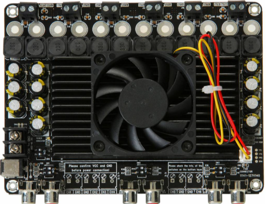
The Amplifier Board 6 x 100 W (Sure Electronics AA-AB34181) is a high-performance audio amplifier board designed to deliver up to 100 watts of output power per channel across six independent channels. Built around the TDA7498 Class-D amplifier chip, this board is ideal for applications requiring high-quality audio output, such as home theater systems, professional audio setups, and multi-room audio systems. Its compact design and efficient power handling make it a versatile choice for both hobbyists and professionals.
Explore Projects Built with Amplifier Board 6 x 100 W
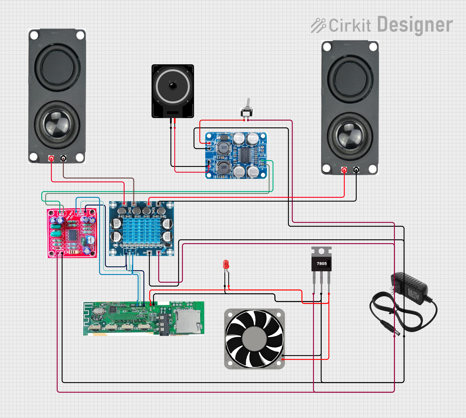
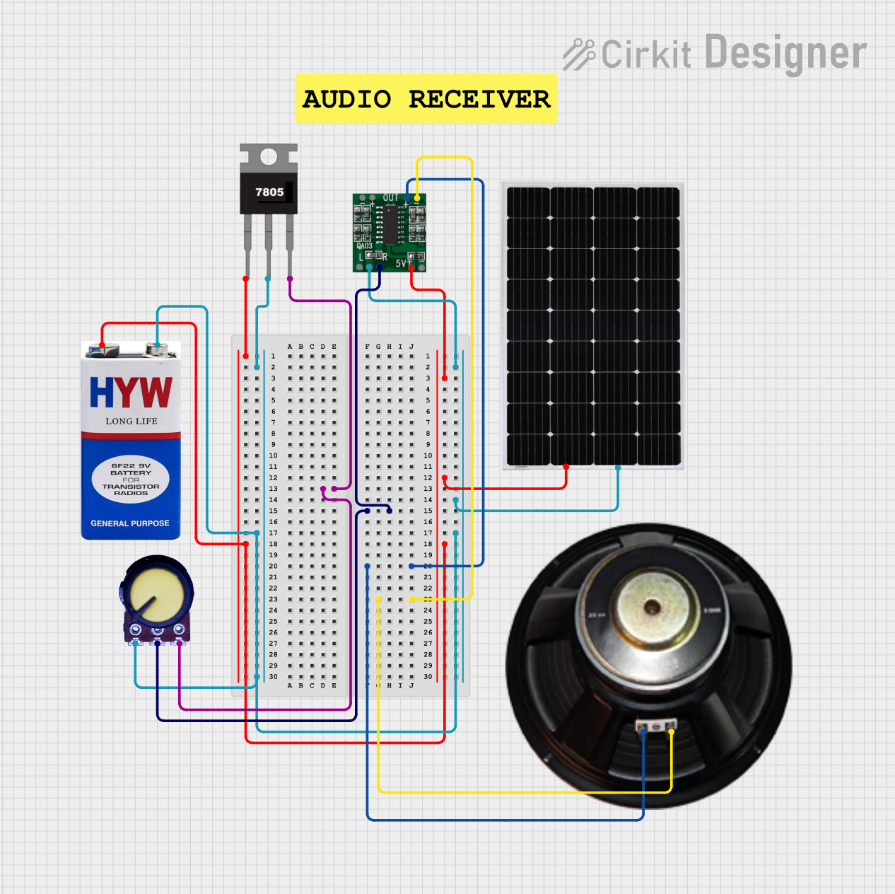
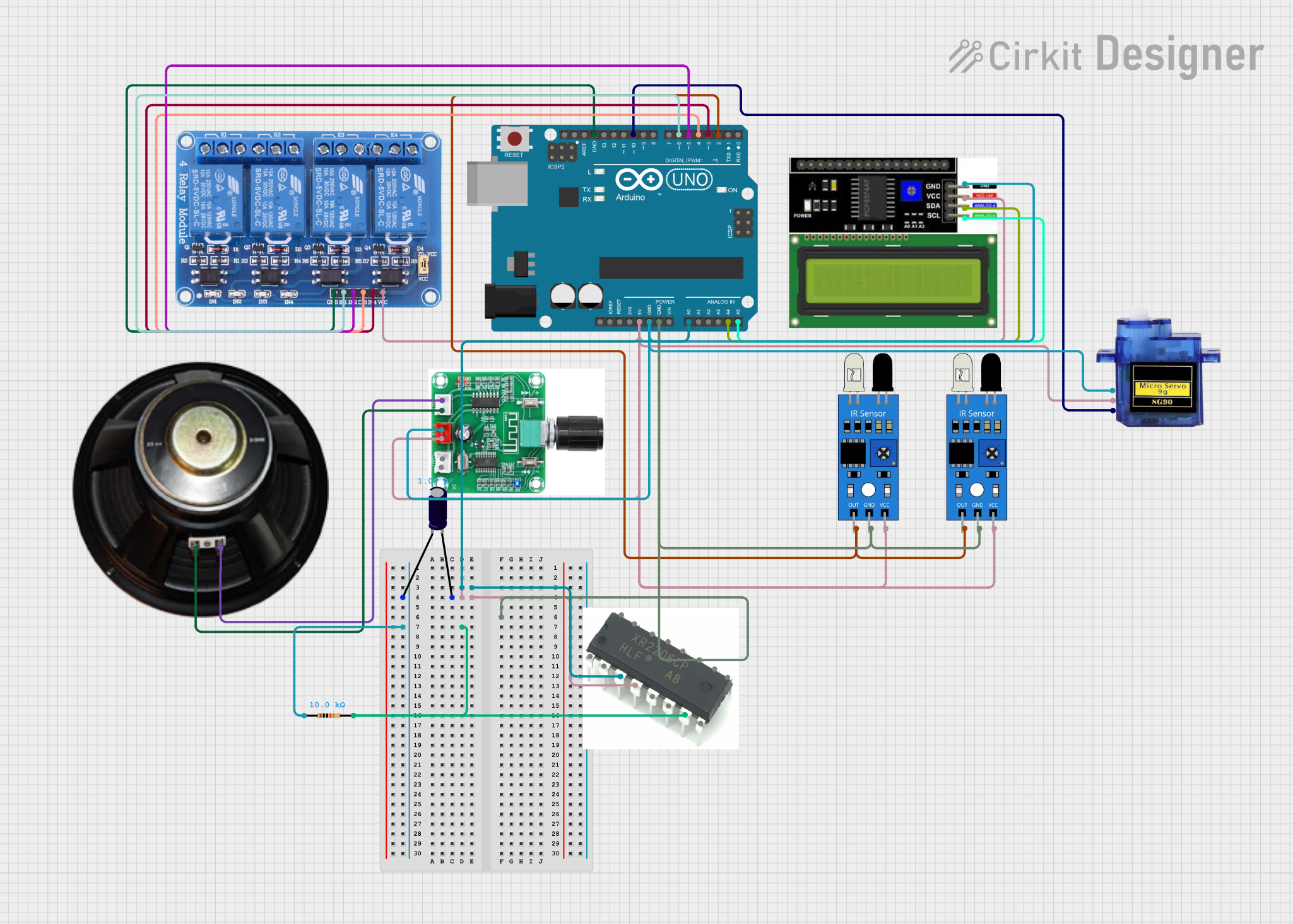
Explore Projects Built with Amplifier Board 6 x 100 W
Common Applications and Use Cases
- Home theater systems with multi-channel audio
- Professional audio systems for events or installations
- Multi-room audio distribution
- DIY speaker projects
- Audio amplification for gaming or multimedia setups
Technical Specifications
The following table outlines the key technical details of the Amplifier Board 6 x 100 W:
| Parameter | Value |
|---|---|
| Manufacturer | Sure Electronics |
| Part Number | AA-AB34181 |
| Amplifier Chip | TDA7498 |
| Output Power | 6 x 100 W (RMS per channel @ 4 Ω, 36 V) |
| Supply Voltage Range | 14 V to 39 V DC |
| Recommended Supply Voltage | 36 V DC |
| Input Sensitivity | 1.5 Vrms |
| Input Impedance | 22 kΩ |
| Output Impedance | 4 Ω to 8 Ω |
| Efficiency | Up to 90% |
| Dimensions | 6.00 x 4.50 inches (152.4 x 114.3 mm) |
| Weight | 0.5 kg |
Pin Configuration and Descriptions
The amplifier board features multiple input and output connections. Below is a detailed description of the pin configuration:
Power Input
| Pin | Label | Description |
|---|---|---|
| 1 | VCC | Positive DC power input (14-39 V) |
| 2 | GND | Ground connection |
Audio Input
| Channel | Pin | Label | Description |
|---|---|---|---|
| CH1 | 1 | IN1+ | Positive audio input for Channel 1 |
| 2 | IN1- | Negative audio input for Channel 1 | |
| CH2 | 3 | IN2+ | Positive audio input for Channel 2 |
| 4 | IN2- | Negative audio input for Channel 2 | |
| CH3 | 5 | IN3+ | Positive audio input for Channel 3 |
| 6 | IN3- | Negative audio input for Channel 3 | |
| CH4 | 7 | IN4+ | Positive audio input for Channel 4 |
| 8 | IN4- | Negative audio input for Channel 4 | |
| CH5 | 9 | IN5+ | Positive audio input for Channel 5 |
| 10 | IN5- | Negative audio input for Channel 5 | |
| CH6 | 11 | IN6+ | Positive audio input for Channel 6 |
| 12 | IN6- | Negative audio input for Channel 6 |
Speaker Output
| Channel | Pin | Label | Description |
|---|---|---|---|
| CH1 | 1 | OUT1+ | Positive speaker output for Channel 1 |
| 2 | OUT1- | Negative speaker output for Channel 1 | |
| CH2 | 3 | OUT2+ | Positive speaker output for Channel 2 |
| 4 | OUT2- | Negative speaker output for Channel 2 | |
| CH3 | 5 | OUT3+ | Positive speaker output for Channel 3 |
| 6 | OUT3- | Negative speaker output for Channel 3 | |
| CH4 | 7 | OUT4+ | Positive speaker output for Channel 4 |
| 8 | OUT4- | Negative speaker output for Channel 4 | |
| CH5 | 9 | OUT5+ | Positive speaker output for Channel 5 |
| 10 | OUT5- | Negative speaker output for Channel 5 | |
| CH6 | 11 | OUT6+ | Positive speaker output for Channel 6 |
| 12 | OUT6- | Negative speaker output for Channel 6 |
Usage Instructions
How to Use the Component in a Circuit
- Power Supply: Connect a DC power supply (14-39 V) to the VCC and GND terminals. A 36 V power supply is recommended for optimal performance.
- Audio Input: Connect the audio source to the input pins (IN1+/- to IN6+/-) using shielded cables to minimize noise.
- Speaker Connection: Connect speakers to the output terminals (OUT1+/- to OUT6+/-). Ensure the speaker impedance matches the board's specifications (4 Ω to 8 Ω).
- Volume Control: Use an external preamp or volume control circuit if needed, as the board does not include onboard volume adjustment.
- Heat Dissipation: Ensure proper ventilation or attach a heatsink to the board to prevent overheating during prolonged use.
Important Considerations and Best Practices
- Power Supply: Use a regulated power supply to avoid voltage fluctuations that could damage the board.
- Speaker Impedance: Ensure the connected speakers have an impedance of 4 Ω to 8 Ω to prevent overloading the amplifier.
- Grounding: Properly ground the board to minimize noise and interference.
- Heat Management: Operate the board in a well-ventilated area or use additional cooling solutions for high-power applications.
Arduino UNO Integration Example
While the amplifier board is not directly programmable, it can be controlled using an Arduino UNO to manage audio input switching or volume control. Below is an example of using the Arduino to control a relay for switching audio inputs:
// Example: Arduino code to control a relay for audio input switching
const int relayPin = 7; // Pin connected to the relay module

void setup() {
  pinMode(relayPin, OUTPUT); // Set relay pin as output
  digitalWrite(relayPin, LOW); // Initialize relay to OFF state
}

void loop() {
  // Turn on the relay to switch audio input
  digitalWrite(relayPin, HIGH);
  delay(5000); // Keep the relay on for 5 seconds

  // Turn off the relay to switch back
  digitalWrite(relayPin, LOW);
  delay(5000); // Keep the relay off for 5 seconds
}
Troubleshooting and FAQs
Common Issues Users Might Face
No Sound Output:
- Check the power supply voltage and ensure it is within the recommended range.
- Verify that the audio input and speaker connections are secure and correctly wired.
- Ensure the audio source is functioning and providing a signal.
Distorted Audio:
- Confirm that the speaker impedance matches the board's specifications (4 Ω to 8 Ω).
- Reduce the input signal level if it exceeds the input sensitivity (1.5 Vrms).
- Check for overheating and ensure proper ventilation.
Overheating:
- Ensure the board is not operating beyond its power limits.
- Use a heatsink or active cooling if necessary.
Solutions and Tips for Troubleshooting
- Use a multimeter to check the voltage at the power input terminals.
- Test the board with a single channel first to isolate potential issues.
- Replace cables or connectors if audio quality is poor or intermittent.
- Consult the manufacturer's datasheet for additional technical details and recommendations.