Cirkit Designer Logo
Cirkit Designer
Your all-in-one circuit design IDE
Home / 
Component Documentation

How to Use PowerSwitch Tail II: Examples, Pinouts, and Specs

Image of PowerSwitch Tail II
Cirkit Designer LogoDesign with PowerSwitch Tail II in Cirkit Designer

Introduction

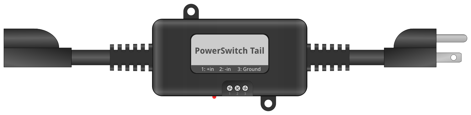
The PowerSwitch Tail II is an innovative electronic component that allows users to safely control high-voltage AC devices using a low-voltage DC control signal. This component is particularly useful for hobbyists, makers, and professionals who need to integrate AC power control into their projects without the complexities and safety concerns of directly handling AC wiring. Common applications include home automation, industrial controls, and interactive art installations.

Explore Projects Built with PowerSwitch Tail II

Use Cirkit Designer to design, explore, and prototype these projects online. Some projects support real-time simulation. Click "Open Project" to start designing instantly!
Aircraft Tow Release Control System with Dual Battery Backup
Image of Queen Air Tow Release Wiring: A project utilizing PowerSwitch Tail II in a practical application
This circuit is designed for a tow release control system in an aircraft, featuring a P68 Tow Control Panel and a Tow Release With Switches assembly. The control panel receives power from two separate aircraft batteries, with one providing main power and the other serving as a backup. The Tow Release With Switches assembly is connected to the control panel, allowing for the actuation of the tow mechanism and providing feedback via an LED indicator.
Cirkit Designer LogoOpen Project in Cirkit Designer
Battery-Powered DC Motor Control System with Speed Regulation
Image of wheel chair: A project utilizing PowerSwitch Tail II in a practical application
This circuit is a motor control system powered by two 12V batteries connected in series, with a 3-position switch to control a PWM motor speed controller. The system includes a pilot lamp for status indication and a NI-MH battery charger powered by an AC source.
Cirkit Designer LogoOpen Project in Cirkit Designer
Battery-Powered DC Motor Control with USB Charging and LED Indicator
Image of lumantas: A project utilizing PowerSwitch Tail II in a practical application
This circuit is designed to charge a Li-ion battery and power a DC motor and a 12V LED. The TP4056 module manages the battery charging process, while the PowerBoost 1000 and MT3608 boost converters step up the voltage to drive the motor and LED, respectively. Two rocker switches control the power flow to the LED and the charging circuit.
Cirkit Designer LogoOpen Project in Cirkit Designer
Dual 5V Power Supply Distribution Circuit with Toggle Switch Control
Image of rfdriver: A project utilizing PowerSwitch Tail II in a practical application
This circuit consists of two 5V 5A power supplies connected to an AC wall plug point, providing DC output through a 12-way connector. The ground connections from both power supplies are interconnected and also connected to the ground pins of two toggle switches. The DC outputs from the power supplies are separately connected to different pins on the 12-way connector, with each power supply output being switchable via one of the toggle switches.
Cirkit Designer LogoOpen Project in Cirkit Designer

Explore Projects Built with PowerSwitch Tail II

Use Cirkit Designer to design, explore, and prototype these projects online. Some projects support real-time simulation. Click "Open Project" to start designing instantly!
Image of Queen Air Tow Release Wiring: A project utilizing PowerSwitch Tail II in a practical application
Aircraft Tow Release Control System with Dual Battery Backup
This circuit is designed for a tow release control system in an aircraft, featuring a P68 Tow Control Panel and a Tow Release With Switches assembly. The control panel receives power from two separate aircraft batteries, with one providing main power and the other serving as a backup. The Tow Release With Switches assembly is connected to the control panel, allowing for the actuation of the tow mechanism and providing feedback via an LED indicator.
Cirkit Designer LogoOpen Project in Cirkit Designer
Image of wheel chair: A project utilizing PowerSwitch Tail II in a practical application
Battery-Powered DC Motor Control System with Speed Regulation
This circuit is a motor control system powered by two 12V batteries connected in series, with a 3-position switch to control a PWM motor speed controller. The system includes a pilot lamp for status indication and a NI-MH battery charger powered by an AC source.
Cirkit Designer LogoOpen Project in Cirkit Designer
Image of lumantas: A project utilizing PowerSwitch Tail II in a practical application
Battery-Powered DC Motor Control with USB Charging and LED Indicator
This circuit is designed to charge a Li-ion battery and power a DC motor and a 12V LED. The TP4056 module manages the battery charging process, while the PowerBoost 1000 and MT3608 boost converters step up the voltage to drive the motor and LED, respectively. Two rocker switches control the power flow to the LED and the charging circuit.
Cirkit Designer LogoOpen Project in Cirkit Designer
Image of rfdriver: A project utilizing PowerSwitch Tail II in a practical application
Dual 5V Power Supply Distribution Circuit with Toggle Switch Control
This circuit consists of two 5V 5A power supplies connected to an AC wall plug point, providing DC output through a 12-way connector. The ground connections from both power supplies are interconnected and also connected to the ground pins of two toggle switches. The DC outputs from the power supplies are separately connected to different pins on the 12-way connector, with each power supply output being switchable via one of the toggle switches.
Cirkit Designer LogoOpen Project in Cirkit Designer

Technical Specifications

Key Technical Details

  • Input Control Voltage: 3-12VDC
  • Max AC Switching Voltage: 120VAC
  • Max AC Current: 15A
  • Control Current: 3mA at 3V to 30mA at 12V
  • Switching: Zero-crossing, for reduced electrical noise
  • Operating Temperature: -40°C to +85°C

Pin Configuration and Descriptions

Pin Number Description Notes
1 AC Neutral (Input) Connect to AC neutral line
2 AC Hot (Input) Connect to AC hot line
3 AC Neutral (Output) Connect to device's AC neutral
4 AC Hot (Output) Connect to device's AC hot
5 DC+ (Control Input) Connect to DC control signal (+)
6 DC- (Control Input) Connect to DC control signal (-)

Usage Instructions

How to Use the PowerSwitch Tail II in a Circuit

  1. Connect the Control Signal:

    • Connect the DC+ pin (5) to the positive terminal of your control signal (e.g., an Arduino digital output pin).
    • Connect the DC- pin (6) to the ground of your control signal source.
  2. Connect the AC Power:

    • Connect the AC Hot (Input) pin (2) to the hot wire of your AC power source.
    • Connect the AC Neutral (Input) pin (1) to the neutral wire of your AC power source.
  3. Connect the Device to be Controlled:

    • Connect the AC Hot (Output) pin (4) to the hot wire of the device you wish to control.
    • Connect the AC Neutral (Output) pin (3) to the neutral wire of the device.

Important Considerations and Best Practices

  • Always ensure that the PowerSwitch Tail II is disconnected from the AC power source before making any connections.
  • Verify that the control signal voltage is within the specified range (3-12VDC).
  • Do not exceed the maximum AC current rating of 15A to prevent damage and ensure safety.
  • Use appropriate wire gauges for AC connections based on the current load of the device being controlled.
  • Ensure that all connections are secure and insulated to prevent accidental contact.

Example Code for Arduino UNO

// Define the control pin for the PowerSwitch Tail II
const int controlPin = 2;

void setup() {
  // Set the control pin as an output
  pinMode(controlPin, OUTPUT);
}

void loop() {
  // Turn on the connected AC device
  digitalWrite(controlPin, HIGH);
  delay(5000); // Keep the device on for 5 seconds

  // Turn off the connected AC device
  digitalWrite(controlPin, LOW);
  delay(5000); // Keep the device off for 5 seconds
}

Troubleshooting and FAQs

Common Issues

  • The AC device does not turn on:

    • Check if the control signal is connected properly and is within the voltage range.
    • Ensure that the AC power source is connected and switched on.
    • Verify that the device being controlled is functioning and not faulty.
  • Intermittent operation or flickering:

    • Confirm that the connections are secure and not loose.
    • Check for any signs of damage to the PowerSwitch Tail II.
    • Ensure that the control signal is stable and not fluctuating.

Solutions and Tips for Troubleshooting

  • Double-check all connections according to the usage instructions.
  • Use a multimeter to verify the presence of the control voltage.
  • If using an Arduino or similar microcontroller, upload a simple test sketch to ensure the control pin is toggling correctly.
  • Replace the PowerSwitch Tail II if it shows signs of damage or if troubleshooting does not resolve the issue.

FAQs

Q: Can I control the PowerSwitch Tail II with a 3.3V control signal? A: Yes, the PowerSwitch Tail II can be activated with a control signal as low as 3V.

Q: Is it safe to handle the PowerSwitch Tail II while it is connected to AC power? A: No, always disconnect the PowerSwitch Tail II from AC power before handling to avoid the risk of electric shock.

Q: Can I use the PowerSwitch Tail II with 240VAC? A: No, the PowerSwitch Tail II is designed for 120VAC. Using it with higher voltages can be dangerous and will damage the unit.

Q: How can I control multiple AC devices with one PowerSwitch Tail II? A: You can control multiple devices if the combined current does not exceed 15A. However, all devices will turn on and off simultaneously. For independent control, use separate PowerSwitch Tail units for each device.