How to Use Wire Splitter -: Examples, Pinouts, and Specs
Introduction
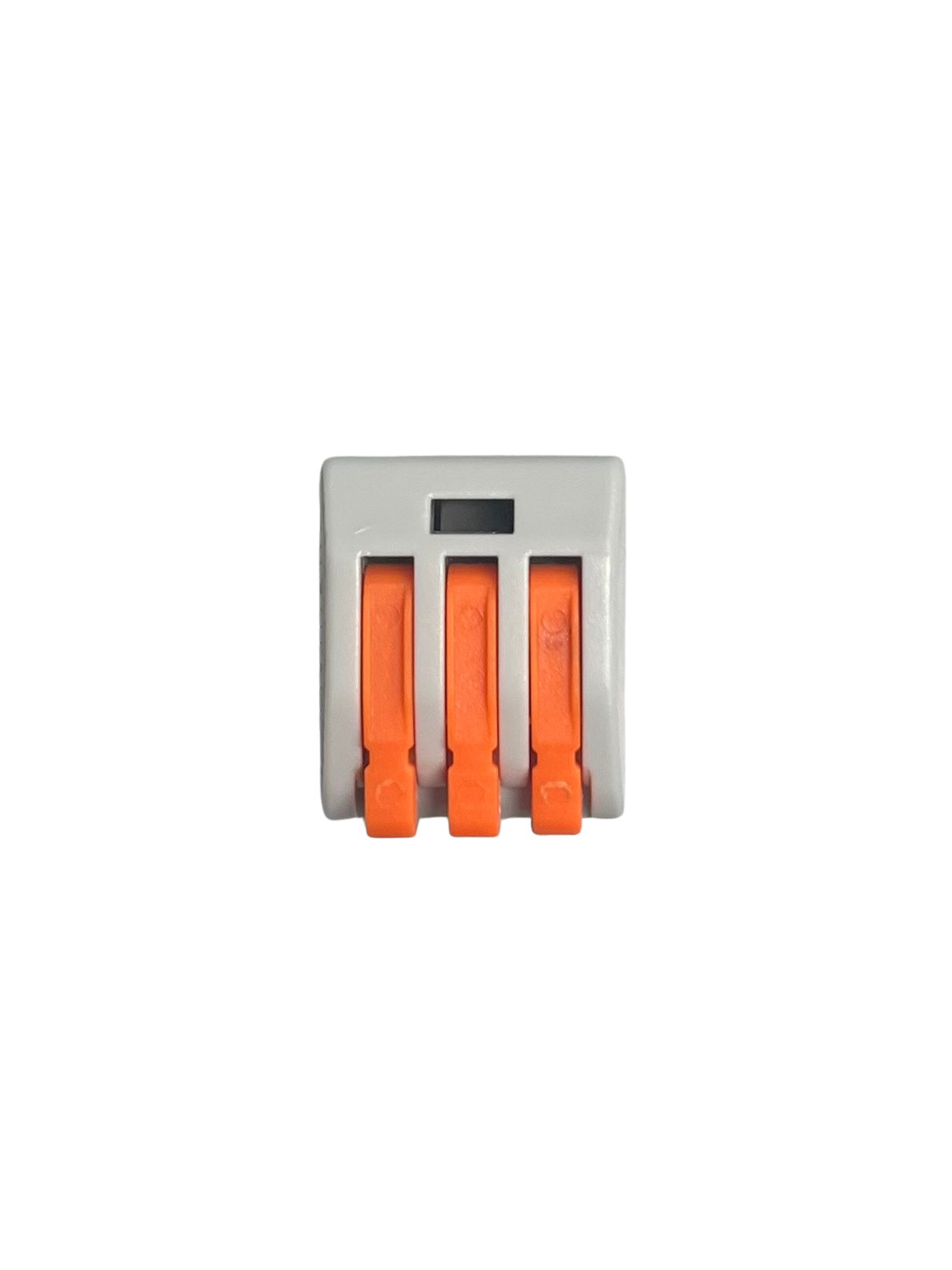
A wire splitter is a device used to divide a single electrical wire into multiple outputs, enabling the distribution of power or signals to multiple devices. It is commonly used in electrical and electronic systems where multiple components need to share a single power source or signal line. Wire splitters are available in various configurations, such as 1-to-2, 1-to-3, or even higher output splits, depending on the application.
Explore Projects Built with Wire Splitter -


Explore Projects Built with Wire Splitter -
Common Applications and Use Cases
- Power distribution in low-voltage DC circuits (e.g., LED strips, fans, or sensors)
- Signal splitting for audio, video, or data transmission
- Connecting multiple devices to a single power adapter
- Automotive wiring for distributing power to accessories
- Prototyping and testing circuits in electronics labs
Technical Specifications
The technical specifications of a wire splitter depend on its design and intended use. Below are general specifications for a typical low-voltage DC wire splitter:
| Parameter | Specification |
|---|---|
| Input Voltage Range | 3V to 24V DC |
| Maximum Current Rating | 5A (varies by model; check product label for details) |
| Number of Outputs | 2, 3, or more (depending on the splitter configuration) |
| Wire Gauge | 18 AWG to 24 AWG (varies by model) |
| Connector Type | Bare wire, DC barrel jack, or custom connectors |
| Insulation Material | PVC or silicone (for durability and flexibility) |
Pin Configuration and Descriptions
For a basic 1-to-2 wire splitter with bare wire ends, the pin configuration is as follows:
| Pin Name | Description |
|---|---|
| Input (+) | Positive input wire (red) |
| Input (-) | Negative input wire (black) |
| Output 1 (+) | Positive output wire for device 1 (red) |
| Output 1 (-) | Negative output wire for device 1 (black) |
| Output 2 (+) | Positive output wire for device 2 (red) |
| Output 2 (-) | Negative output wire for device 2 (black) |
For splitters with connectors, refer to the product-specific pinout diagram.
Usage Instructions
How to Use the Component in a Circuit
- Identify the Input and Output Wires: Check the markings or color codes on the wire splitter to identify the input and output connections.
- Connect the Input Wires: Attach the input wires of the splitter to the power source or signal line. Ensure proper polarity (e.g., red for positive, black for negative).
- Connect the Output Wires: Attach the output wires to the devices you want to power or connect. Match the polarity of the wires to the devices.
- Secure the Connections: Use soldering, wire nuts, or connectors to ensure secure and reliable connections.
- Test the Circuit: Power on the circuit and verify that all connected devices are functioning as expected.
Important Considerations and Best Practices
- Current Rating: Ensure the total current drawn by all connected devices does not exceed the splitter's maximum current rating.
- Voltage Compatibility: Verify that the input voltage is within the specified range for the splitter and connected devices.
- Wire Gauge: Use a wire splitter with an appropriate wire gauge to handle the current without overheating.
- Insulation: Ensure that all connections are properly insulated to prevent short circuits or electrical hazards.
- Avoid Overloading: Do not connect more devices than the splitter is designed to handle.
Example: Connecting a Wire Splitter to an Arduino UNO
A wire splitter can be used to power multiple components (e.g., sensors and LEDs) from the Arduino's 5V pin. Below is an example code snippet for controlling two LEDs connected via a wire splitter:
// Example code for controlling two LEDs connected via a wire splitter
// Ensure the total current drawn by the LEDs does not exceed the Arduino's limit

const int led1Pin = 9; // Pin connected to LED 1
const int led2Pin = 10; // Pin connected to LED 2

void setup() {
  pinMode(led1Pin, OUTPUT); // Set LED 1 pin as output
  pinMode(led2Pin, OUTPUT); // Set LED 2 pin as output
}

void loop() {
  digitalWrite(led1Pin, HIGH); // Turn on LED 1
  digitalWrite(led2Pin, HIGH); // Turn on LED 2
  delay(1000); // Wait for 1 second

  digitalWrite(led1Pin, LOW); // Turn off LED 1
  digitalWrite(led2Pin, LOW); // Turn off LED 2
  delay(1000); // Wait for 1 second
}
Troubleshooting and FAQs
Common Issues Users Might Face
Devices Not Powering On:
- Cause: Incorrect wiring or loose connections.
- Solution: Double-check the wiring and ensure all connections are secure.
Overheating Wires:
- Cause: Exceeding the current rating of the wire splitter.
- Solution: Reduce the load by disconnecting some devices or use a splitter with a higher current rating.
Voltage Drop Across Outputs:
- Cause: High current draw or long wire lengths.
- Solution: Use a splitter with thicker wires (lower AWG) or reduce the load.
Short Circuit:
- Cause: Exposed wires touching each other.
- Solution: Insulate all connections properly and check for exposed wires.
FAQs
Q1: Can I use a wire splitter for AC power?
A1: Most wire splitters are designed for low-voltage DC applications. For AC power, use a splitter specifically rated for AC voltage and current.
Q2: How many devices can I connect to a wire splitter?
A2: The number of devices depends on the splitter's design and current rating. Ensure the total current draw does not exceed the splitter's maximum rating.
Q3: Can I daisy-chain multiple wire splitters?
A3: Yes, but be cautious of the total current draw and potential voltage drops. Overloading the circuit can cause overheating or damage.
Q4: What wire gauge should I use for high-current applications?
A4: Use a splitter with a lower AWG (thicker wire) for high-current applications to minimize resistance and heat buildup.