How to Use PZEM-017: Examples, Pinouts, and Specs

Introduction
The PZEM-017 is a multifunctional energy meter manufactured by PeaceFair. It is designed to measure key electrical parameters in AC circuits, including voltage, current, power, energy, and frequency. This versatile module is equipped with a digital display for real-time monitoring and supports UART communication, making it ideal for integration with microcontrollers such as Arduino or Raspberry Pi.
Explore Projects Built with PZEM-017


Explore Projects Built with PZEM-017
Common Applications and Use Cases
- Monitoring energy consumption in residential or industrial settings
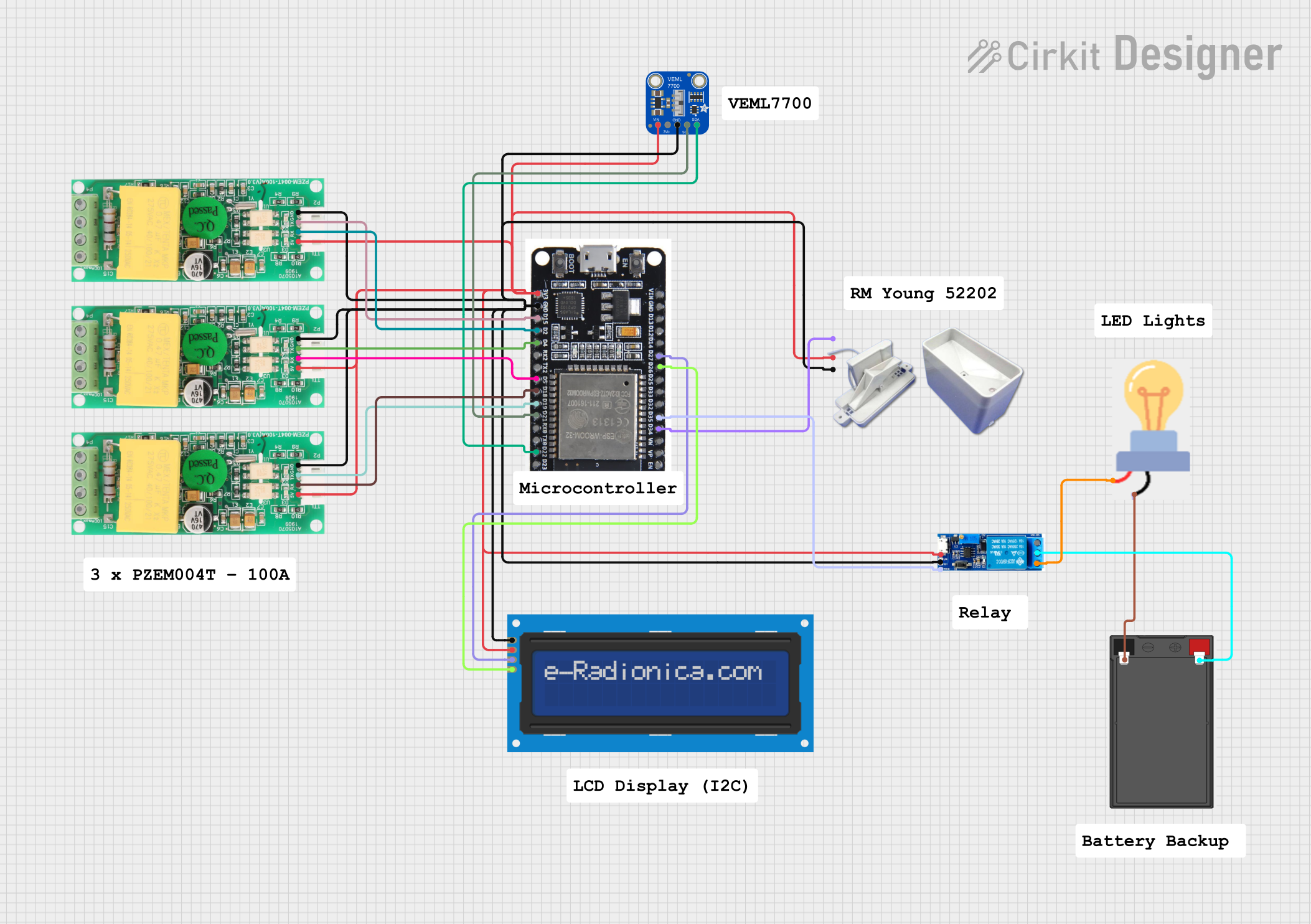
- Integration into IoT systems for smart energy management
- Real-time power monitoring in renewable energy systems
- Load analysis and diagnostics in electrical circuits
Technical Specifications
The following table outlines the key technical details of the PZEM-017:
| Parameter | Specification |
|---|---|
| Voltage Range | 80V - 260V AC |
| Current Range | 0A - 100A (with external current transformer) |
| Power Range | 0W - 22kW |
| Energy Range | 0kWh - 9999kWh |
| Frequency Range | 45Hz - 65Hz |
| Communication Interface | UART (9600 baud rate, 8N1 format) |
| Power Supply | 5V DC (external power required) |
| Accuracy | ±0.5% |
| Operating Temperature | -10°C to 60°C |
| Dimensions | 70mm x 40mm x 30mm |
Pin Configuration and Descriptions
The PZEM-017 has a simple pinout for power, communication, and measurement connections. The table below describes each pin:
| Pin Name | Description |
|---|---|
| V+ | Positive DC input for powering the module (5V DC). |
| V- | Negative DC input (ground). |
| TX | UART transmit pin for data communication. |
| RX | UART receive pin for data communication. |
| L | Live wire connection for AC voltage measurement. |
| N | Neutral wire connection for AC voltage measurement. |
| CT+ | Positive terminal for the external current transformer (CT). |
| CT- | Negative terminal for the external current transformer (CT). |
Usage Instructions
How to Use the PZEM-017 in a Circuit
- Power the Module: Connect the V+ and V- pins to a 5V DC power source.
- Connect the AC Circuit:
- Attach the live (L) and neutral (N) wires of the AC circuit to the corresponding L and N terminals on the PZEM-017.
- Ensure proper insulation and safety precautions when working with high-voltage AC circuits.
- Connect the Current Transformer (CT):
- Place the CT around the live wire of the AC circuit.
- Connect the CT+ and CT- terminals to the corresponding pins on the PZEM-017.
- Establish UART Communication:
- Connect the TX and RX pins of the PZEM-017 to the RX and TX pins of a microcontroller (e.g., Arduino UNO).
- Use a common ground between the PZEM-017 and the microcontroller.
Important Considerations and Best Practices
- Always ensure proper insulation and safety when working with high-voltage AC circuits.
- Use a compatible current transformer (CT) rated for the expected current range.
- Avoid reversing the TX and RX connections when interfacing with a microcontroller.
- Ensure the UART baud rate is set to 9600 and the communication format is 8N1 (8 data bits, no parity, 1 stop bit).
Example: Using the PZEM-017 with Arduino UNO
Below is an example Arduino sketch to read data from the PZEM-017 using UART:
#include <SoftwareSerial.h>

// Define RX and TX pins for SoftwareSerial
SoftwareSerial pzemSerial(10, 11); // RX = pin 10, TX = pin 11

void setup() {
  Serial.begin(9600); // Initialize Serial Monitor
  pzemSerial.begin(9600); // Initialize UART communication with PZEM-017

  Serial.println("PZEM-017 Energy Meter Example");
}

void loop() {
  // Request data from PZEM-017
  byte request[] = {0x01, 0x04, 0x00, 0x00, 0x00, 0x0A, 0x70, 0x0D};
  pzemSerial.write(request, sizeof(request));

  delay(100); // Wait for response

  // Read response from PZEM-017
  byte response[25];
  int len = pzemSerial.readBytes(response, sizeof(response));

  if (len > 0) {
    Serial.print("Response: ");
    for (int i = 0; i < len; i++) {
      Serial.print(response[i], HEX);
      Serial.print(" ");
    }
    Serial.println();
  } else {
    Serial.println("No response from PZEM-017");
  }

  delay(1000); // Wait before next request
}
Notes:
- The example code sends a Modbus RTU request to the PZEM-017 and prints the raw response.
- For detailed data parsing, refer to the PZEM-017 Modbus protocol documentation.
Troubleshooting and FAQs
Common Issues and Solutions
No Data Received from the PZEM-017:
- Verify the TX and RX connections between the PZEM-017 and the microcontroller.
- Ensure the UART baud rate is set to 9600 and the communication format is 8N1.
- Check the power supply to the PZEM-017 (5V DC).
Incorrect Measurements:
- Ensure the current transformer (CT) is properly connected and placed around the live wire.
- Verify that the live (L) and neutral (N) wires are correctly connected to the PZEM-017.
Module Not Powering On:
- Check the V+ and V- connections to ensure a stable 5V DC supply.
- Inspect for loose or damaged wires.
FAQs
Q: Can the PZEM-017 measure DC circuits?
A: No, the PZEM-017 is designed specifically for AC circuits and cannot measure DC parameters.
Q: What is the maximum current the PZEM-017 can measure?
A: The PZEM-017 can measure up to 100A when used with a compatible current transformer (CT).
Q: Can I use the PZEM-017 with a Raspberry Pi?
A: Yes, the PZEM-017 can be interfaced with a Raspberry Pi using UART communication. Ensure proper voltage level shifting if required.