How to Use Load Cell - Red/white/black/green: Examples, Pinouts, and Specs
Introduction
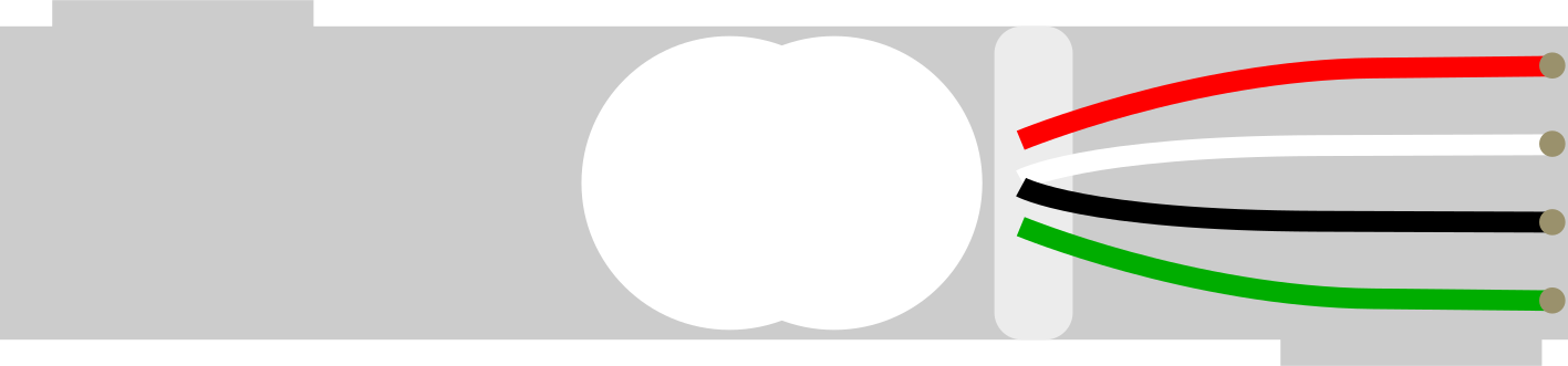
A load cell is an electronic device that is used to measure weight or force. It converts a force into an electrical signal, acting as a transducer. This particular load cell comes with four wires colored red, white, black, and green, which are used for making connections to a measuring instrument or a microcontroller like an Arduino. Load cells are widely used in scales, industrial systems, and tension measurement devices.
Explore Projects Built with Load Cell - Red/white/black/green
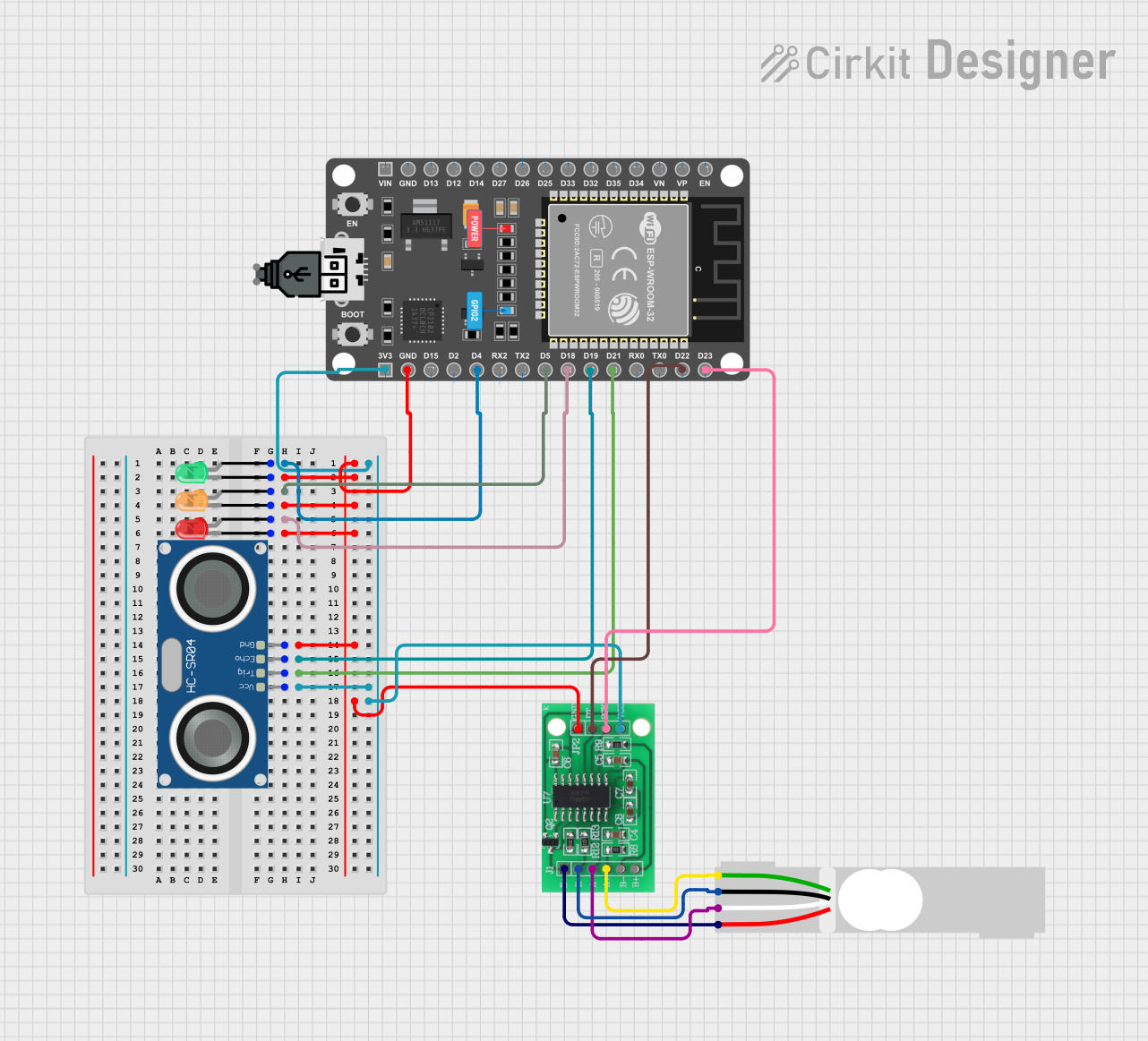
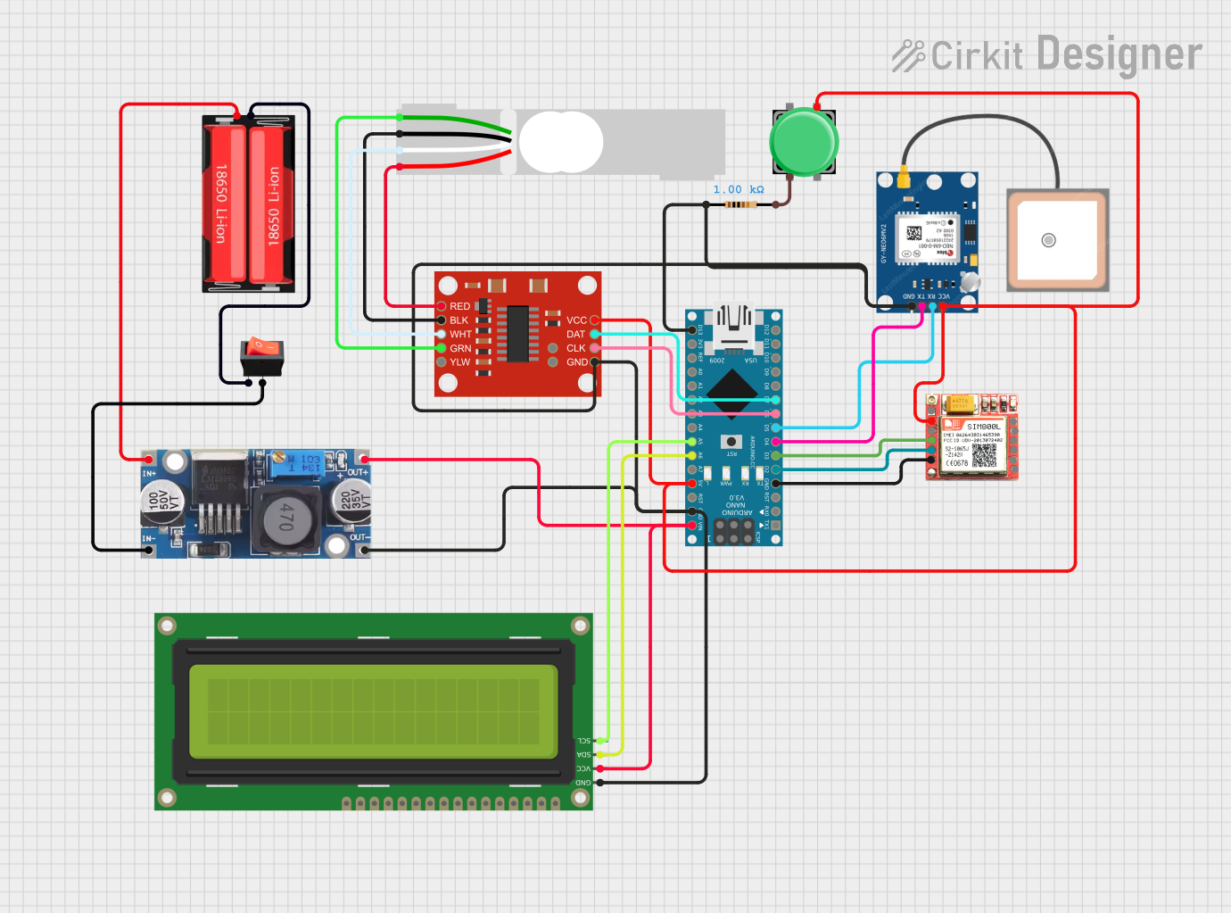
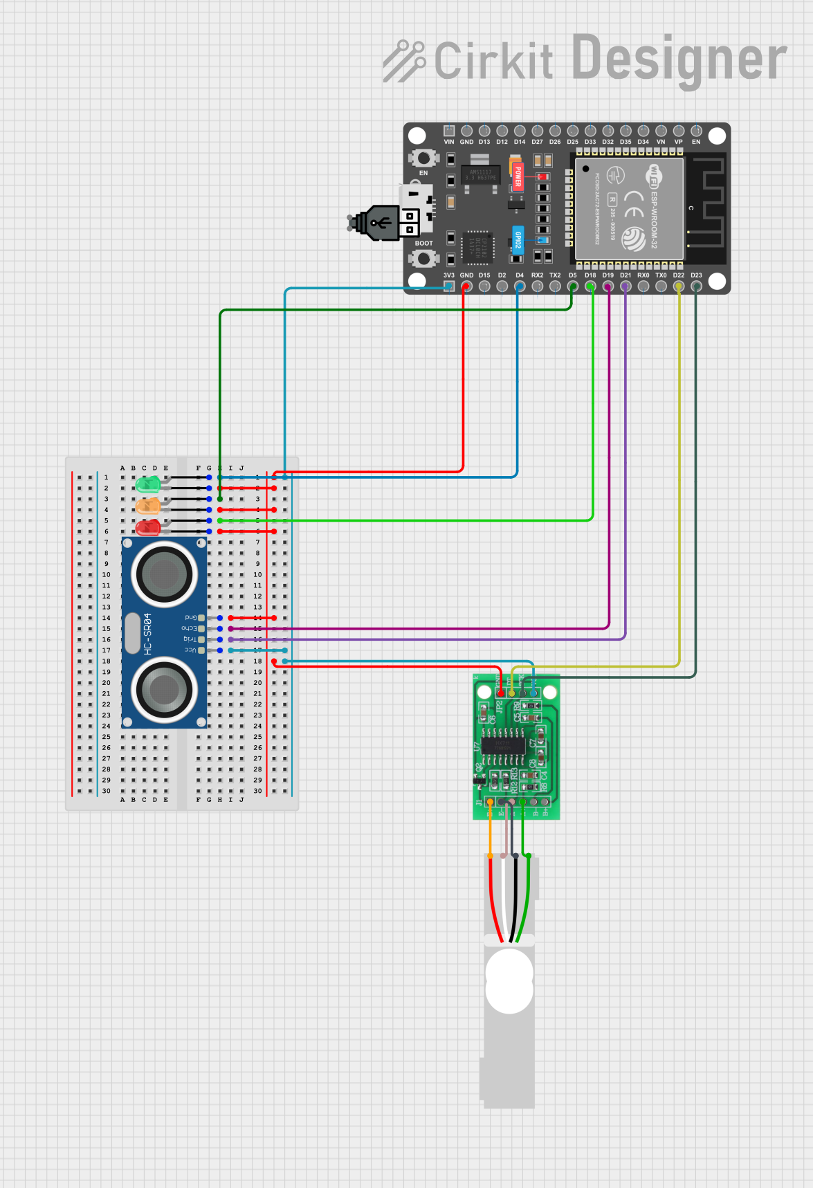

Explore Projects Built with Load Cell - Red/white/black/green
Common Applications and Use Cases
- Industrial weighing systems
- Electronic scales
- Force measurement in testing equipment
- Feedback control systems for force application
Technical Specifications
Key Technical Details
- Rated Load: Specified in datasheet (e.g., 5kg, 10kg, 50kg)
- Rated Output: Typically 1mV/V to 3mV/V at full scale
- Excitation Voltage: Recommended voltage for optimal performance (e.g., 5V to 12V)
- Input Resistance: Resistance between the excitation leads (e.g., 350 ohms)
- Output Resistance: Resistance between the signal leads (e.g., 350 ohms)
- Nonlinearity: Deviation from the straight line in the output curve (e.g., ±0.02% F.S.)
- Hysteresis: Difference in output at the same load depending on whether the load is increasing or decreasing (e.g., ±0.02% F.S.)
- Temperature Effect on Output: Change in output due to temperature variations (e.g., ±0.0015% F.S./°C)
Pin Configuration and Descriptions
| Color | Function | Description |
|---|---|---|
| Red | Excitation + (E+) | Connects to the positive side of the excitation voltage |
| Black | Excitation - (E-) | Connects to the negative side of the excitation voltage |
| Green | Signal + (S+) | Connects to the positive input of the signal amplifier |
| White | Signal - (S-) | Connects to the negative input of the signal amplifier |
Usage Instructions
How to Use the Component in a Circuit
- Connect the Wires: Connect the red and black wires to the excitation voltage source. The red wire goes to the positive terminal, and the black wire goes to the negative terminal.
- Signal Wires: Connect the green and white wires to the signal amplifier or data acquisition system. The green wire is the positive signal, and the white wire is the negative signal.
- Calibration: Before using the load cell, it must be calibrated with known weights to ensure accurate measurements.
- Mounting: The load cell should be mounted securely, with the force applied perpendicularly to the sensing area.
Important Considerations and Best Practices
- Avoid mechanical shock and side loads, as they can affect the readings.
- Ensure that the load cell is used within its specified weight range to prevent damage.
- Keep the load cell and its connections free from moisture and corrosive chemicals.
- Use shielded cables for the signal wires to minimize electrical noise.
Troubleshooting and FAQs
Common Issues
- Inaccurate Readings: Ensure the load cell is calibrated correctly. Check for any mechanical obstructions or misalignments.
- No Output Signal: Verify that all connections are secure and the excitation voltage is within the specified range.
- Drifting Readings: This could be due to temperature changes or unstable mounting. Ensure the load cell is mounted securely and in a temperature-stable environment.
Solutions and Tips for Troubleshooting
- Calibration: Regularly recalibrate the load cell to maintain accuracy.
- Connections: Double-check wire connections if the load cell is not responding as expected.
- Environmental Factors: Minimize exposure to extreme temperatures and vibrations.
FAQs
Q: Can I use a different voltage for excitation? A: It is recommended to use the excitation voltage specified in the datasheet to ensure accurate measurements.
Q: How do I know if my load cell is damaged? A: A damaged load cell may produce erratic or no signal. If you suspect damage, test the cell with known weights or consult the manufacturer.
Q: Can I extend the wires of the load cell? A: Yes, but use shielded cables and proper connectors to avoid signal degradation.
Example Arduino Code
// Load Cell Example Code for Arduino UNO
#include "HX711.h"

// HX711 circuit wiring
const int LOADCELL_DOUT_PIN = 3;
const int LOADCELL_SCK_PIN = 2;

HX711 scale;

void setup() {
  Serial.begin(9600);
  scale.begin(LOADCELL_DOUT_PIN, LOADCELL_SCK_PIN);
}

void loop() {
  if (scale.is_ready()) {
    long reading = scale.read();
    Serial.print("Raw reading: ");
    Serial.println(reading);
  } else {
    Serial.println("Load cell not ready");
  }
}
Note: This example assumes the use of an HX711 amplifier module, which is commonly used with load cells for signal amplification and digitization. The HX711 library must be installed in the Arduino IDE. The LOADCELL_DOUT_PIN and LOADCELL_SCK_PIN constants should be set to the appropriate digital pins connected to the HX711 module.