
How to Use lm2529: Examples, Pinouts, and Specs
 Design with lm2529 in Cirkit Designer
Introduction
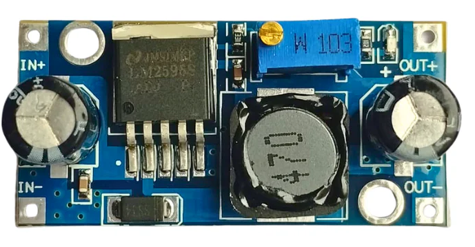
The LM2529 is a high-efficiency step-down (buck) voltage regulator designed to convert a higher input voltage into a stable, lower output voltage. It is widely used in power management applications due to its adjustable output voltage, wide input voltage range, and integrated protection features such as thermal shutdown and current limiting. The LM2529 is ideal for powering microcontrollers, sensors, and other low-voltage devices in embedded systems, industrial equipment, and consumer electronics.
Explore Projects Built with lm2529
 Open Project in Cirkit Designer
 Open Project in Cirkit Designer
 Open Project in Cirkit Designer
 Open Project in Cirkit Designer
Explore Projects Built with lm2529
Open Project in Cirkit DesignerOpen Project in Cirkit DesignerOpen Project in Cirkit DesignerOpen Project in Cirkit DesignerCommon Applications
- Powering microcontrollers and digital circuits
- Battery-powered devices
- Industrial automation systems
- Consumer electronics
- Distributed power systems
Technical Specifications
Key Specifications
| Parameter | Value |
|---|---|
| Input Voltage Range | 4.5V to 40V |
| Output Voltage Range | Adjustable (1.2V to 37V) |
| Output Current | Up to 3A |
| Efficiency | Up to 90% |
| Switching Frequency | 150 kHz |
| Thermal Shutdown | Yes |
| Current Limiting | Yes |
| Package Type | TO-220 or TO-263 |
Pin Configuration and Descriptions
TO-220 Package
| Pin Number | Pin Name | Description |
|---|---|---|
| 1 | VIN | Input voltage (4.5V to 40V) |
| 2 | VOUT | Regulated output voltage |
| 3 | GND | Ground connection |
| 4 | FB | Feedback pin for setting the output voltage |
| 5 | EN | Enable pin to turn the regulator on/off |
TO-263 Package
| Pin Number | Pin Name | Description |
|---|---|---|
| 1 | VIN | Input voltage (4.5V to 40V) |
| 2 | VOUT | Regulated output voltage |
| 3 | GND | Ground connection |
| 4 | FB | Feedback pin for setting the output voltage |
| 5 | EN | Enable pin to turn the regulator on/off |
Usage Instructions
How to Use the LM2529 in a Circuit
- Input Voltage: Connect the input voltage (VIN) to the VIN pin. Ensure the input voltage is within the range of 4.5V to 40V.
- Output Voltage: Use a resistor divider network connected to the FB pin to set the desired output voltage. The formula for the output voltage is: [ V_{OUT} = V_{REF} \times \left(1 + \frac{R1}{R2}\right) ] where ( V_{REF} ) is typically 1.2V.
- Enable Pin: Connect the EN pin to VIN to enable the regulator. To disable the regulator, pull the EN pin to ground.
- Output Capacitor: Place a low-ESR capacitor (e.g., 22µF) at the output to ensure stability and reduce voltage ripple.
- Input Capacitor: Add a capacitor (e.g., 10µF) at the input to filter noise and stabilize the input voltage.
- Inductor Selection: Choose an inductor with a suitable current rating and inductance value to ensure efficient operation.
Important Considerations
- Thermal Management: Ensure proper heat dissipation by using a heatsink or adequate PCB copper area for the LM2529.
- Current Limiting: Do not exceed the maximum output current of 3A to avoid triggering the current limiting feature.
- PCB Layout: Minimize the trace length between the input/output capacitors and the LM2529 to reduce noise and improve stability.
Example: Using LM2529 with Arduino UNO
The LM2529 can be used to power an Arduino UNO by stepping down a 12V input to 5V. Below is an example circuit and Arduino code:
Circuit Connections
- Connect a 12V DC power supply to the VIN pin of the LM2529.
- Set the output voltage to 5V using a resistor divider network on the FB pin.
- Connect the VOUT pin of the LM2529 to the 5V pin of the Arduino UNO.
- Connect the GND pin of the LM2529 to the GND pin of the Arduino UNO.
Arduino Code
// Example code to blink an LED using Arduino UNO powered by LM2529
const int ledPin = 13; // Pin connected to the onboard LED

void setup() {
  pinMode(ledPin, OUTPUT); // Set the LED pin as an output
}

void loop() {
  digitalWrite(ledPin, HIGH); // Turn the LED on
  delay(1000); // Wait for 1 second
  digitalWrite(ledPin, LOW); // Turn the LED off
  delay(1000); // Wait for 1 second
}
Troubleshooting and FAQs
Common Issues and Solutions
No Output Voltage
- Cause: The EN pin is not connected or is pulled low.
- Solution: Ensure the EN pin is connected to VIN or a high logic level.
Output Voltage is Unstable
- Cause: Insufficient output capacitance or poor PCB layout.
- Solution: Add a low-ESR capacitor (e.g., 22µF) at the output and minimize trace lengths.
Excessive Heat
- Cause: High input voltage or insufficient heat dissipation.
- Solution: Use a heatsink or increase the PCB copper area for better thermal management.
Output Voltage is Incorrect
- Cause: Incorrect resistor values in the feedback network.
- Solution: Verify the resistor values and recalculate the output voltage using the formula.
FAQs
Q1: Can the LM2529 be used with a 24V input?
A1: Yes, the LM2529 supports input voltages up to 40V, so 24V is within its operating range.
Q2: What is the minimum output voltage of the LM2529?
A2: The minimum output voltage is 1.2V, which is determined by the internal reference voltage.
Q3: Can I use the LM2529 without a heatsink?
A3: It depends on the input voltage, output current, and ambient temperature. For high-power applications, a heatsink or proper thermal management is recommended.
Q4: How do I calculate the inductor value for my application?
A4: The inductor value depends on the input voltage, output voltage, switching frequency, and desired ripple current. Refer to the LM2529 datasheet for detailed guidelines on inductor selection.