How to Use Adafruit 1.2 Inch 8x8 LED Matrix Backpack Yellow-Green: Examples, Pinouts, and Specs
Introduction
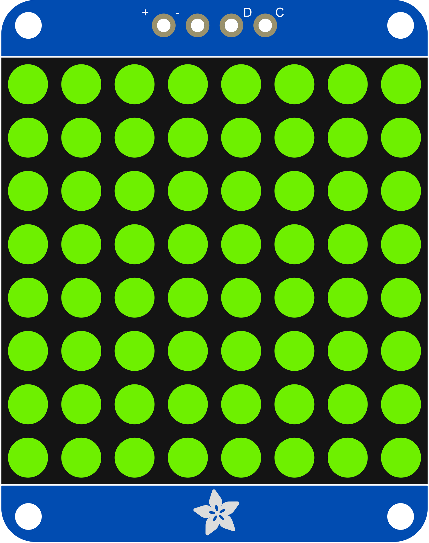
The Adafruit 1.2 Inch 8x8 LED Matrix Backpack with Yellow-Green LEDs is a compact and versatile electronic component that combines an 8x8 LED matrix display with an integrated driver board, or "backpack." This component simplifies the process of controlling multiple LEDs, making it an ideal choice for creating displays for indicators, simple animations, and text. Common applications include DIY clocks, counters, and game displays.
Explore Projects Built with Adafruit 1.2 Inch 8x8 LED Matrix Backpack Yellow-Green

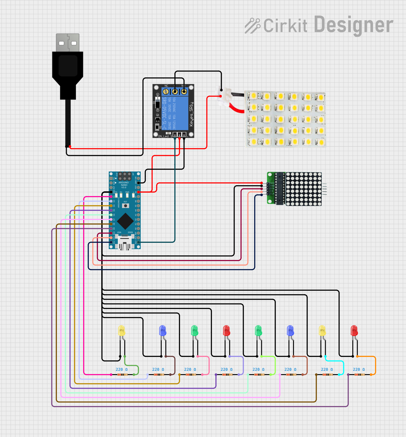

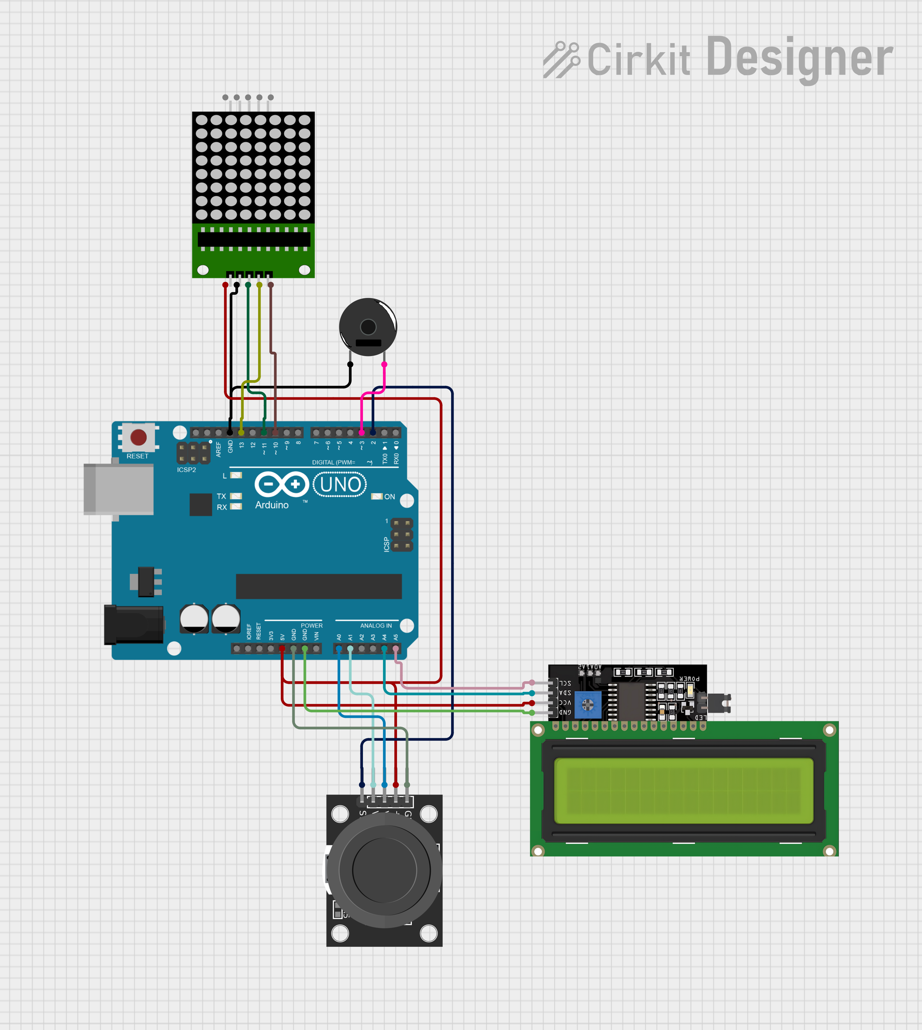
Explore Projects Built with Adafruit 1.2 Inch 8x8 LED Matrix Backpack Yellow-Green
Technical Specifications
Key Technical Details
- Display Color: Yellow-Green
- Matrix Dimensions: 1.2 inches (diagonal)
- Resolution: 8x8 pixels
- Operating Voltage: 4.5V - 5.5V
- Max Current (with all LEDs on): ~320 mA
- Interface: I2C
- I2C Addresses: Selectable between 0x70 - 0x77
Pin Configuration and Descriptions
| Pin Number | Name | Description |
|---|---|---|
| 1 | GND | Ground connection |
| 2 | VCC | Power supply (4.5V - 5.5V) |
| 3 | SDA | I2C Data line |
| 4 | SCL | I2C Clock line |
| 5 | ADDR | Address selection (connect to GND or VCC) |
| 6 | RST | Reset pin (optional use) |
Usage Instructions
Integrating with a Circuit
To use the Adafruit 1.2 Inch 8x8 LED Matrix Backpack in a circuit:
- Connect the GND pin to the ground of your power supply.
- Connect the VCC pin to a 4.5V - 5.5V power supply.
- Connect the SDA and SCL pins to the I2C data and clock lines of your microcontroller (e.g., Arduino UNO).
- If necessary, set the ADDR pin to select the I2C address.
- Optionally, connect the RST pin to a digital output on your microcontroller if you wish to control the reset function.
Important Considerations and Best Practices
- Ensure that the power supply does not exceed the recommended voltage range.
- If multiple LED matrices are used, make sure to set unique I2C addresses for each.
- Avoid running all LEDs at maximum brightness to prevent excessive power consumption and heat generation.
- Use pull-up resistors on the I2C lines if your microcontroller does not have built-in pull-ups.
Example Code for Arduino UNO
#include <Wire.h>
#include <Adafruit_GFX.h>
#include <Adafruit_LEDBackpack.h>

Adafruit_8x8matrix matrix = Adafruit_8x8matrix();

void setup() {
  matrix.begin(0x70); // Initialize with the I2C addr 0x70 (default)
}

void loop() {
  matrix.clear();
  matrix.drawPixel(0, 0, LED_ON); // Turn on a single LED in the top-left corner
  matrix.writeDisplay(); // Write the changes to the display
  delay(500);

  matrix.clear();
  matrix.writeDisplay(); // Clear the display
  delay(500);
}
Troubleshooting and FAQs
Common Issues
- Display not lighting up: Check the power connections and ensure the I2C address is correctly set.
- Dim or flickering LEDs: Verify that the power supply is within the specified voltage range and can provide sufficient current.
- Garbled or incorrect display: Ensure there are no conflicts with the I2C address if using multiple devices on the same bus.
Solutions and Tips for Troubleshooting
- Double-check wiring, especially the I2C connections.
- Use the
i2cdetectutility or similar to confirm the device is recognized on the I2C bus. - Review your code to ensure proper initialization and update of the display.
- Consult the Adafruit forums and support channels for additional assistance.
FAQs
Q: Can I daisy-chain multiple LED matrix backpacks? A: Yes, you can connect multiple matrices in series by connecting the SDA and SCL lines and setting unique I2C addresses for each.
Q: How do I control the brightness of the LEDs?
A: The Adafruit LED Backpack library provides functions to control the brightness. Use matrix.setBrightness(brightness) where brightness is a value from 0 (dim) to 15 (bright).
Q: What is the maximum number of LED matrix backpacks I can control with one microcontroller? A: You can control up to 8 matrices on a single I2C bus, as there are 8 selectable I2C addresses available (0x70 to 0x77).