How to Use PLC: Examples, Pinouts, and Specs
Introduction
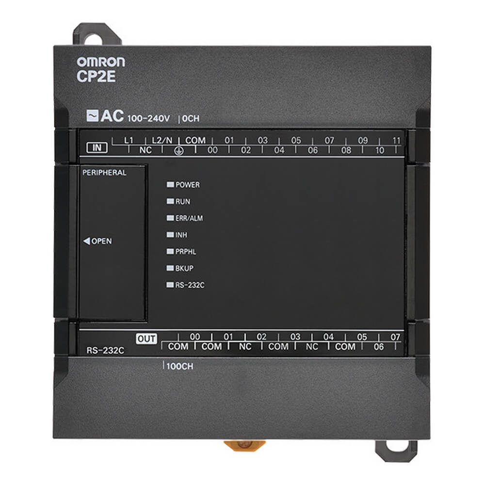
The Omron Model CP2E-E20DR-A is a compact and versatile Programmable Logic Controller (PLC) designed for industrial automation applications. It is part of Omron's CP2E series, which is optimized for small to medium-sized automation systems. This PLC is ideal for controlling electromechanical processes such as machinery on factory assembly lines, amusement rides, and lighting systems. Its robust design and advanced features make it suitable for a wide range of industrial environments.
Explore Projects Built with PLC


Explore Projects Built with PLC
Common Applications and Use Cases
- Factory automation and assembly line control
- Process monitoring and control in manufacturing
- Automated lighting and HVAC systems
- Amusement park ride control systems
- Water treatment and pumping systems
- Small-scale industrial robotics
Technical Specifications
The following table outlines the key technical details of the Omron CP2E-E20DR-A PLC:
| Specification | Details |
|---|---|
| Power Supply Voltage | 24 VDC |
| Input Voltage Range | 24 VDC (Digital Inputs) |
| Number of Inputs | 12 (Digital Inputs) |
| Number of Outputs | 8 (Relay Outputs) |
| Output Type | Relay (SPST-NO) |
| Maximum Output Current | 2 A per point |
| Communication Ports | RS-232C, RS-485, Ethernet |
| Programming Language | Ladder Diagram (LD), Function Block Diagram (FBD), Structured Text (ST) |
| Memory Capacity | 20 KB (Program Memory) |
| Operating Temperature | -10°C to 55°C |
| Dimensions | 90 mm x 85 mm x 67 mm |
| Weight | Approximately 300 g |
Pin Configuration and Descriptions
The CP2E-E20DR-A has a total of 20 I/O points, with 12 digital inputs and 8 relay outputs. The pin configuration is as follows:
Input Pins
| Pin Number | Description | Voltage Range |
|---|---|---|
| 0-11 | Digital Inputs (IN0-IN11) | 24 VDC |
Output Pins
| Pin Number | Description | Output Type | Max Current |
|---|---|---|---|
| 12-19 | Relay Outputs (OUT0-OUT7) | SPST-NO | 2 A per point |
Communication Ports
| Port | Description | Protocol |
|---|---|---|
| RS-232C | Serial Communication | Modbus, Custom |
| RS-485 | Serial Communication | Modbus RTU |
| Ethernet | Network Communication | TCP/IP |
Usage Instructions
How to Use the CP2E-E20DR-A in a Circuit
- Power Supply Connection: Connect a 24 VDC power supply to the PLC's power input terminals. Ensure proper polarity to avoid damage.
- Input Connections: Connect sensors, switches, or other input devices to the digital input pins (IN0-IN11). Use 24 VDC signals for proper operation.
- Output Connections: Connect actuators, relays, or other output devices to the relay output pins (OUT0-OUT7). Ensure the load does not exceed 2 A per point.
- Communication Setup: Use the RS-232C, RS-485, or Ethernet ports to connect the PLC to other devices or a network. Configure the communication protocol as needed.
- Programming: Use Omron's CX-Programmer software to write and upload programs to the PLC. The software supports Ladder Diagram (LD), Function Block Diagram (FBD), and Structured Text (ST) programming languages.
Important Considerations and Best Practices
- Always verify the power supply voltage and polarity before powering the PLC.
- Use proper shielding and grounding for communication cables to minimize electrical noise.
- Avoid exceeding the maximum current rating of the output pins to prevent damage.
- Regularly back up the PLC program to avoid data loss in case of hardware failure.
- Ensure the operating environment is within the specified temperature range (-10°C to 55°C).
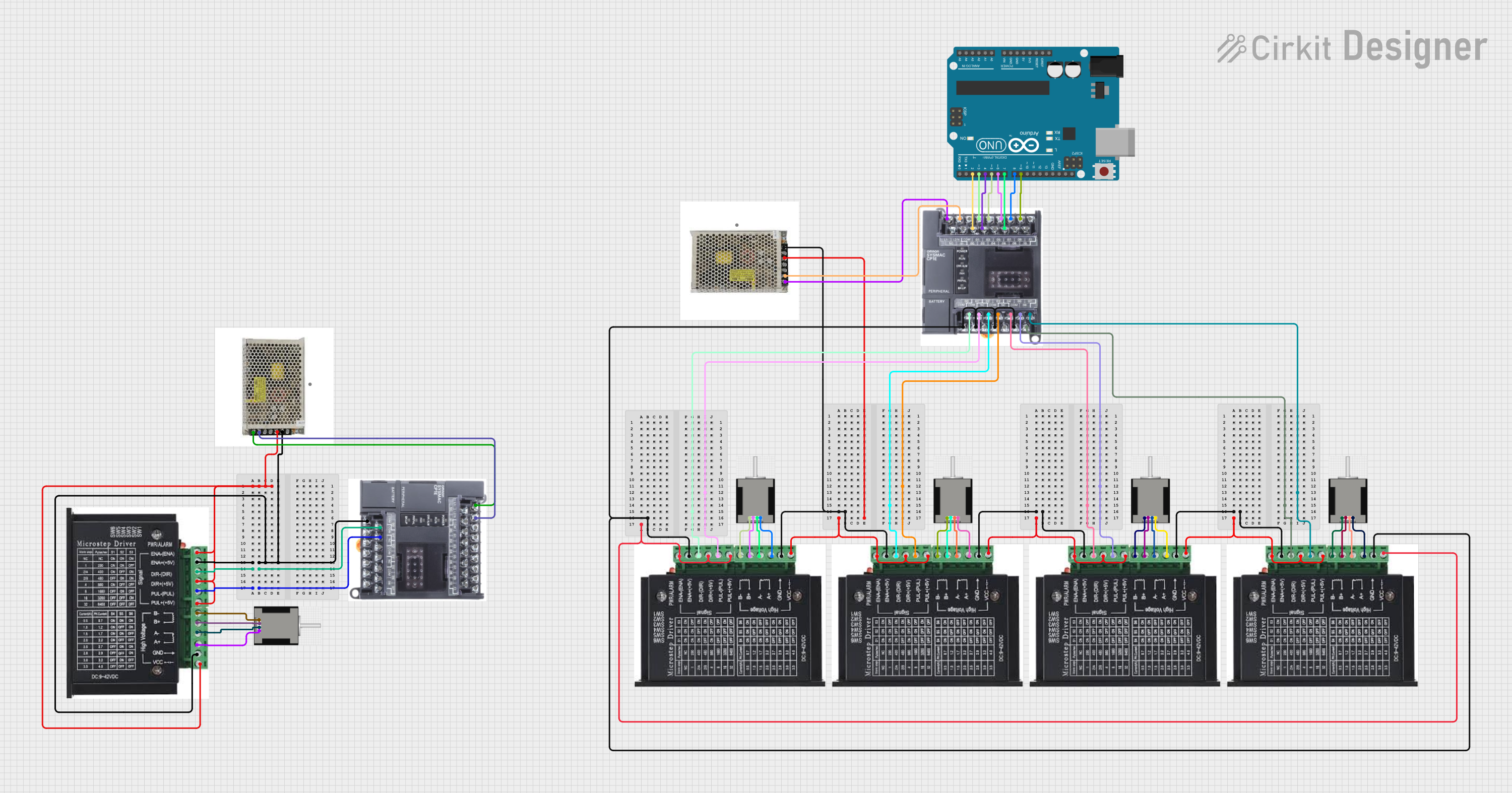
Example Code for Arduino UNO Communication
The CP2E-E20DR-A can communicate with an Arduino UNO via the RS-232C port. Below is an example code snippet for sending data from the Arduino to the PLC:
#include <SoftwareSerial.h>

// Define RX and TX pins for SoftwareSerial
SoftwareSerial plcSerial(10, 11); // RX = pin 10, TX = pin 11

void setup() {
  // Initialize serial communication with the PLC
  plcSerial.begin(9600); // Set baud rate to 9600
  Serial.begin(9600);    // For debugging on the Serial Monitor

  Serial.println("Arduino to PLC communication started.");
}

void loop() {
  // Example: Send a command to the PLC
  String command = "START"; // Replace with actual PLC command
  plcSerial.println(command); // Send command to PLC

  // Check for response from PLC
  if (plcSerial.available()) {
    String response = plcSerial.readString();
    Serial.println("PLC Response: " + response); // Print response to Serial Monitor
  }

  delay(1000); // Wait 1 second before sending the next command
}
Notes:
- Use a TTL-to-RS232 converter module to interface the Arduino UNO with the PLC's RS-232C port.
- Ensure the baud rate and communication settings (e.g., parity, stop bits) match between the Arduino and the PLC.
Troubleshooting and FAQs
Common Issues and Solutions
PLC Not Powering On
- Cause: Incorrect power supply voltage or polarity.
- Solution: Verify the power supply voltage is 24 VDC and check the polarity.
Inputs Not Responding
- Cause: Faulty wiring or incompatible input voltage.
- Solution: Check the wiring and ensure the input devices provide 24 VDC signals.
Outputs Not Activating
- Cause: Load exceeds the maximum current rating or incorrect wiring.
- Solution: Verify the load current is within the 2 A limit and check the wiring.
Communication Failure
- Cause: Incorrect communication settings or faulty cables.
- Solution: Ensure the baud rate, parity, and stop bits match between devices. Use shielded cables to reduce noise.
FAQs
Q: Can the CP2E-E20DR-A be used in outdoor environments?
A: The PLC is designed for indoor use. If used outdoors, ensure it is housed in a weatherproof enclosure.
Q: What software is required to program the PLC?
A: Omron's CX-Programmer software is required for programming the CP2E-E20DR-A.
Q: Can the PLC handle analog inputs?
A: The CP2E-E20DR-A does not have built-in analog input capability. Use an external analog-to-digital converter if needed.
Q: How do I reset the PLC to factory settings?
A: Refer to the Omron CP2E series user manual for detailed instructions on performing a factory reset.