Cirkit Designer
Your all-in-one circuit design IDE
Home /
Component Documentation
How to Use P10 RGB PINS: Examples, Pinouts, and Specs
Introduction
P10 RGB PINS are connectors designed to interface with P10 RGB LED display modules. These connectors facilitate the transmission of power and data signals, enabling the control of the display. P10 RGB LED modules are commonly used in large-scale digital displays, such as billboards, advertising screens, and information boards. The P10 RGB PINS ensure a reliable connection between the control hardware and the LED modules, making them essential for seamless display operation.
Explore Projects Built with P10 RGB PINS
Raspberry Pi Pico W RGB LED Controller with Resistors
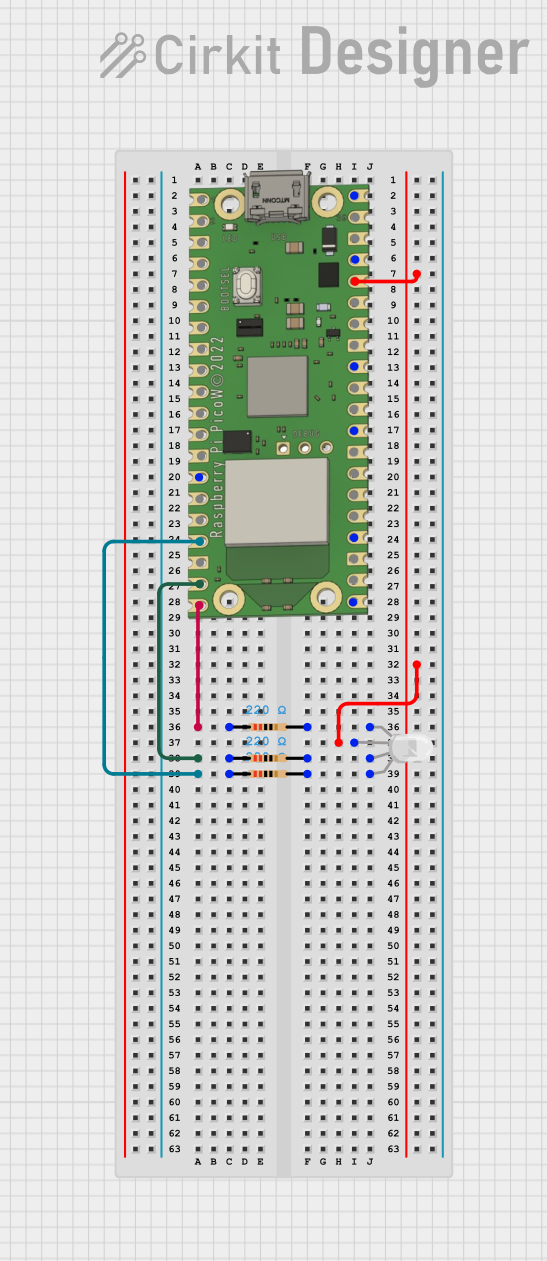
This circuit uses a Raspberry Pi Pico W to control an RGB LED through three 220-ohm resistors connected to its GPIO pins. The Pico W provides 3.3V power to the common anode of the RGB LED, allowing for color control via the GPIO pins GP13, GP14, and GP15.
ESP32-Controlled RGB LED Lighting System
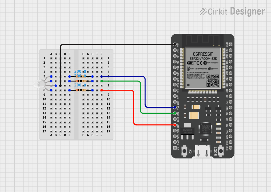
This circuit features an ESP32 microcontroller connected to an RGB LED through three 200 Ohm resistors. Each color channel (Red, Green, Blue) of the LED is connected to a GPIO pin (G13, G12, G14 respectively) on the ESP32 via a resistor. The common anode of the RGB LED is directly connected to the 3.3V power supply from the ESP32, allowing the microcontroller to control the color of the LED by PWM signals on the GPIO pins.
Wi-Fi Controlled RGB Lighting with Raspberry Pi Pico W
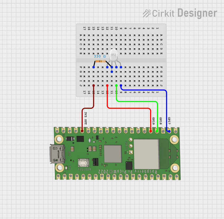
This circuit features a Raspberry Pi Pico W microcontroller connected to an RGB LED through GPIO pins GP17, GP18, and GP19 for controlling the blue, green, and red channels, respectively. A resistor is connected between the 3V3 OUT pin of the Pico and the common cathode of the RGB LED to limit the current. The embedded code suggests the Pico W is configured for Wi-Fi connectivity and MQTT communication to control the LED and possibly other peripherals not shown in the circuit, with additional functionality for sensor monitoring and display output.
Raspberry Pi Controlled RGB LED Array
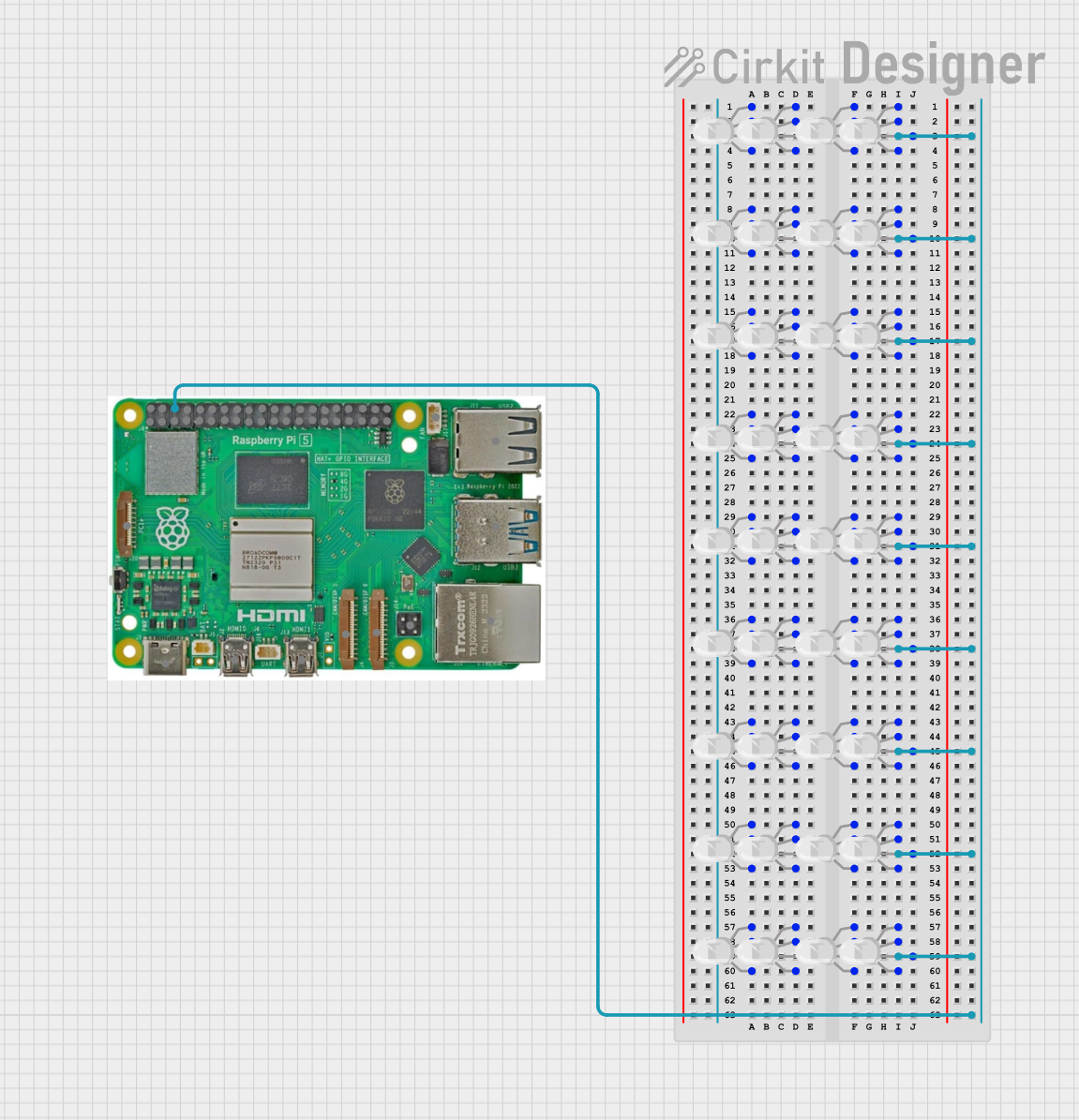
This circuit consists of multiple RGB LEDs connected to a Raspberry Pi 5. The common cathode (COM) pins of the LEDs are connected to the ground (GND) of the Raspberry Pi, while the individual red (R), green (G), and blue (B) pins are grouped and interconnected, allowing for synchronized color control across the LEDs.
Explore Projects Built with P10 RGB PINS
Raspberry Pi Pico W RGB LED Controller with Resistors
This circuit uses a Raspberry Pi Pico W to control an RGB LED through three 220-ohm resistors connected to its GPIO pins. The Pico W provides 3.3V power to the common anode of the RGB LED, allowing for color control via the GPIO pins GP13, GP14, and GP15.
ESP32-Controlled RGB LED Lighting System
This circuit features an ESP32 microcontroller connected to an RGB LED through three 200 Ohm resistors. Each color channel (Red, Green, Blue) of the LED is connected to a GPIO pin (G13, G12, G14 respectively) on the ESP32 via a resistor. The common anode of the RGB LED is directly connected to the 3.3V power supply from the ESP32, allowing the microcontroller to control the color of the LED by PWM signals on the GPIO pins.
Wi-Fi Controlled RGB Lighting with Raspberry Pi Pico W
This circuit features a Raspberry Pi Pico W microcontroller connected to an RGB LED through GPIO pins GP17, GP18, and GP19 for controlling the blue, green, and red channels, respectively. A resistor is connected between the 3V3 OUT pin of the Pico and the common cathode of the RGB LED to limit the current. The embedded code suggests the Pico W is configured for Wi-Fi connectivity and MQTT communication to control the LED and possibly other peripherals not shown in the circuit, with additional functionality for sensor monitoring and display output.
Raspberry Pi Controlled RGB LED Array
This circuit consists of multiple RGB LEDs connected to a Raspberry Pi 5. The common cathode (COM) pins of the LEDs are connected to the ground (GND) of the Raspberry Pi, while the individual red (R), green (G), and blue (B) pins are grouped and interconnected, allowing for synchronized color control across the LEDs.
Technical Specifications
Key Technical Details
| Parameter | Value |
|---|---|
| Voltage Rating | 5V DC |
| Current Rating | 2A per pin |
| Power Rating | 10W per pin |
| Connector Type | 16-pin dual-row header |
| Pin Pitch | 2.54 mm |
| Operating Temp | -40°C to 85°C |
| Contact Material | Phosphor Bronze with Gold Plating |
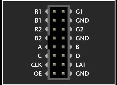
Pin Configuration and Descriptions
| Pin Number | Pin Name | Description |
|---|---|---|
| 1 | GND | Ground |
| 2 | GND | Ground |
| 3 | R1 | Red Data for Upper Half |
| 4 | G1 | Green Data for Upper Half |
| 5 | B1 | Blue Data for Upper Half |
| 6 | R2 | Red Data for Lower Half |
| 7 | G2 | Green Data for Lower Half |
| 8 | B2 | Blue Data for Lower Half |
| 9 | A | Row Address A |
| 10 | B | Row Address B |
| 11 | C | Row Address C |
| 12 | D | Row Address D |
| 13 | CLK | Clock Signal |
| 14 | LAT | Latch Signal |
| 15 | OE | Output Enable |
| 16 | VCC | +5V Power Supply |
Usage Instructions
How to Use the Component in a Circuit
- Power Supply Connection: Connect the VCC pin to a 5V DC power supply and the GND pins to the ground of the power supply.
- Data Signal Connection: Connect the R1, G1, B1, R2, G2, and B2 pins to the corresponding data output pins of your control hardware (e.g., Arduino, Raspberry Pi).
- Address and Control Signals: Connect the A, B, C, and D pins to the row address output pins of your control hardware. Connect the CLK, LAT, and OE pins to the clock, latch, and output enable pins of your control hardware, respectively.
Important Considerations and Best Practices
- Power Supply: Ensure that the power supply can provide sufficient current for the LED display module. Each P10 module can draw significant current, especially when displaying bright colors.
- Signal Integrity: Use short and thick wires for power connections to minimize voltage drops. For data and control signals, use twisted pair cables or shielded cables to reduce noise and signal degradation.
- Heat Management: P10 LED modules can generate heat during operation. Ensure adequate ventilation or cooling to prevent overheating.
Example Code for Arduino UNO
Below is an example code to interface a P10 RGB LED module with an Arduino UNO:
#include <Adafruit_GFX.h>   // Include Adafruit graphics library
#include <RGBmatrixPanel.h> // Include RGB matrix panel library

#define CLK 8  // Clock pin
#define LAT 10 // Latch pin
#define OE  9  // Output enable pin
#define A   A0 // Row address A
#define B   A1 // Row address B
#define C   A2 // Row address C
#define D   A3 // Row address D

RGBmatrixPanel matrix(A, B, C, D, CLK, LAT, OE, false, 64); // Initialize matrix

void setup() {
  matrix.begin(); // Initialize the matrix
  matrix.fillScreen(matrix.Color333(0, 0, 0)); // Clear the screen
}

void loop() {
  matrix.fillScreen(matrix.Color333(0, 0, 0)); // Clear the screen
  matrix.setCursor(1, 1); // Set cursor position
  matrix.setTextColor(matrix.Color333(7, 0, 0)); // Set text color to red
  matrix.print("Hello, World!"); // Display text
  delay(1000); // Wait for 1 second
}
Troubleshooting and FAQs
Common Issues Users Might Face
- No Display Output: Ensure that all connections are secure and that the power supply is adequate. Check the control signals for proper timing and levels.
- Flickering Display: This can be caused by insufficient power supply or poor signal integrity. Ensure that the power supply can handle the current demand and use proper cabling for data and control signals.
- Incorrect Colors: Verify that the data signals are correctly connected to the corresponding pins. Check the software configuration for any errors in color data handling.
Solutions and Tips for Troubleshooting
- Check Connections: Double-check all connections to ensure they are secure and correctly placed.
- Use a Multimeter: Measure the voltage at the VCC and GND pins to ensure the power supply is providing the correct voltage.
- Test with Simple Code: Start with simple test code to verify basic functionality before moving on to more complex programs.
- Consult Datasheets: Refer to the datasheets of both the P10 RGB LED module and the control hardware for detailed information on signal requirements and timing.
By following this documentation, users can effectively interface with P10 RGB LED display modules using P10 RGB PINS, ensuring reliable and vibrant display performance.