How to Use Adafruit QT Py ESP32 Pico: Examples, Pinouts, and Specs
Introduction
The Adafruit QT Py ESP32 Pico is a compact microcontroller board powered by the ESP32 chip. It is designed for seamless integration with a wide range of sensors and peripherals, making it an excellent choice for Internet of Things (IoT) projects. With built-in Wi-Fi and Bluetooth capabilities, this board enables wireless communication and control, making it suitable for smart home devices, wearable technology, and other connected applications.
Explore Projects Built with Adafruit QT Py ESP32 Pico


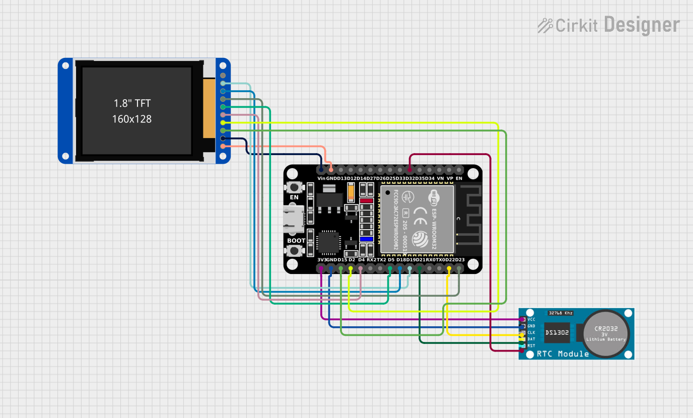
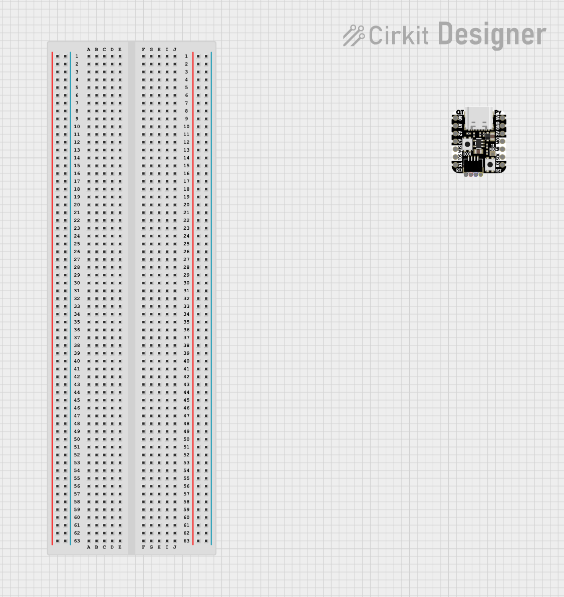
Explore Projects Built with Adafruit QT Py ESP32 Pico
Common Applications and Use Cases
- IoT devices and smart home automation
- Wireless sensor networks
- Wearable electronics
- Robotics and remote control systems
- Prototyping and educational projects
Technical Specifications
The Adafruit QT Py ESP32 Pico is packed with features that make it versatile and powerful for various applications. Below are its key technical details:
Key Technical Details
| Specification | Value |
|---|---|
| Microcontroller | ESP32 Pico (dual-core, 32-bit Xtensa LX6) |
| Clock Speed | Up to 240 MHz |
| Flash Memory | 4 MB |
| SRAM | 520 KB |
| Wi-Fi | 802.11 b/g/n (2.4 GHz) |
| Bluetooth | Bluetooth Classic and BLE (v4.2) |
| Operating Voltage | 3.3V |
| Input Voltage (USB-C) | 5V |
| GPIO Pins | 13 (multi-function) |
| Communication Interfaces | I2C, SPI, UART |
| ADC Channels | 6 |
| PWM Outputs | 8 |
| Dimensions | 22.9 mm x 17.8 mm |
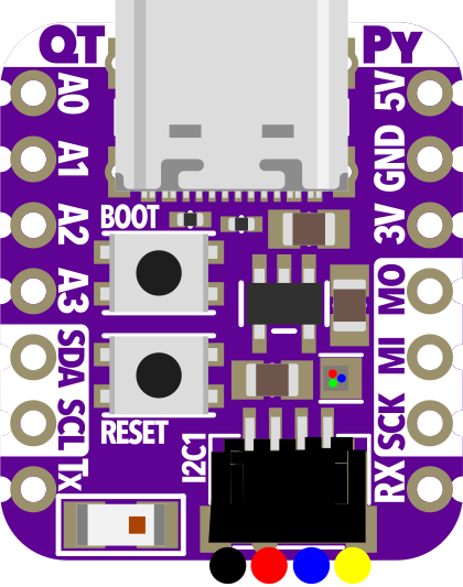
Pin Configuration and Descriptions
The Adafruit QT Py ESP32 Pico features a compact pinout. Below is the pin configuration:
| Pin Name | Function(s) | Description |
|---|---|---|
| 3V3 | Power Output | 3.3V output for powering external components. |
| GND | Ground | Common ground for the circuit. |
| A0 | ADC, GPIO | Analog input or digital GPIO. |
| A1 | ADC, GPIO | Analog input or digital GPIO. |
| SDA | I2C Data | I2C data line (can also be used as GPIO). |
| SCL | I2C Clock | I2C clock line (can also be used as GPIO). |
| TX | UART TX, GPIO | UART transmit or digital GPIO. |
| RX | UART RX, GPIO | UART receive or digital GPIO. |
| SCK | SPI Clock, GPIO | SPI clock line or digital GPIO. |
| MISO | SPI Data In, GPIO | SPI data input or digital GPIO. |
| MOSI | SPI Data Out, GPIO | SPI data output or digital GPIO. |
| D0-D3 | GPIO, PWM | General-purpose I/O pins with PWM capability. |
| USB-C | Power, Data | USB-C connector for power and programming. |
Usage Instructions
The Adafruit QT Py ESP32 Pico is easy to use in a variety of projects. Below are the steps and best practices for using this microcontroller.
How to Use the Component in a Circuit
Powering the Board:
- Use a USB-C cable to power the board (5V input).
- Alternatively, supply 3.3V directly to the 3V3 pin.
Connecting Peripherals:
- Use the GPIO pins to connect sensors, actuators, or other peripherals.
- For I2C devices, connect to the SDA and SCL pins.
- For SPI devices, use the SCK, MISO, and MOSI pins.
Programming the Board:
- Install the Arduino IDE or CircuitPython environment.
- Select the appropriate board (e.g., "ESP32 Dev Module") in the IDE.
- Connect the board to your computer via USB-C and upload your code.
Important Considerations and Best Practices
- Voltage Levels: Ensure all connected peripherals operate at 3.3V logic levels to avoid damaging the board.
- Wi-Fi and Bluetooth: Avoid placing the board in metal enclosures, as this can interfere with wireless communication.
- Heat Management: The ESP32 chip can get warm during operation. Ensure proper ventilation if used in enclosed spaces.
- Firmware Updates: Regularly update the firmware to ensure compatibility and access to the latest features.
Example Code for Arduino UNO Integration
Below is an example of how to use the Adafruit QT Py ESP32 Pico to read a temperature sensor and send the data over Wi-Fi:
#include <WiFi.h> // Include the Wi-Fi library

// Replace with your network credentials
const char* ssid = "Your_SSID";
const char* password = "Your_PASSWORD";

void setup() {
  Serial.begin(115200); // Initialize serial communication
  delay(1000);

  // Connect to Wi-Fi
  Serial.print("Connecting to Wi-Fi");
  WiFi.begin(ssid, password);
  while (WiFi.status() != WL_CONNECTED) {
    delay(500);
    Serial.print(".");
  }
  Serial.println("\nConnected to Wi-Fi!");
}

void loop() {
  // Example: Read a sensor value (replace with actual sensor code)
  int sensorValue = analogRead(A0); // Read analog value from pin A0
  Serial.print("Sensor Value: ");
  Serial.println(sensorValue);

  delay(1000); // Wait for 1 second before the next reading
}
Troubleshooting and FAQs
Common Issues and Solutions
Board Not Detected by Computer:
- Ensure the USB-C cable supports data transfer (not just charging).
- Check that the correct drivers are installed for the ESP32.
Wi-Fi Connection Fails:
- Double-check the SSID and password in your code.
- Ensure the Wi-Fi network is within range and operational.
Code Upload Fails:
- Verify that the correct board and port are selected in the Arduino IDE.
- Press the reset button on the board before uploading.
Peripherals Not Working:
- Confirm that the peripherals are connected to the correct pins.
- Check for loose connections or incorrect voltage levels.
FAQs
Q: Can I use 5V peripherals with this board?
A: No, the GPIO pins operate at 3.3V logic levels. Use a level shifter for 5V peripherals.
Q: Does the board support CircuitPython?
A: Yes, the Adafruit QT Py ESP32 Pico is compatible with CircuitPython for easy programming.
Q: How do I reset the board?
A: Press the reset button located on the board to restart it.
Q: Can I use this board for battery-powered projects?
A: Yes, you can power the board using a 3.7V LiPo battery with a suitable regulator.
By following this documentation, you can effectively use the Adafruit QT Py ESP32 Pico in your projects and troubleshoot common issues with ease.