Cirkit Designer
Your all-in-one circuit design IDE
Home /
Component Documentation
How to Use AUTOMATIC SOLAR: Examples, Pinouts, and Specs
Introduction
The Automatic Solar is a device designed to optimize the efficiency of solar panels by automatically adjusting their position to track the sun's movement throughout the day. This ensures maximum sunlight exposure, significantly improving energy generation. The device is equipped with sensors and a motorized mechanism to align the solar panels with the sun's position in real-time.
Explore Projects Built with AUTOMATIC SOLAR
Solar-Powered Home Energy System with Automatic Transfer Switch and Battery Backup

This circuit is a solar power system with an automatic transfer switch (ATS) that manages power from both a solar panel and an AC supply. The solar panel charges a battery through a solar charge controller, and the power inverter converts the stored DC power to AC, which is then distributed through an MCB to a socket. The ATS ensures seamless switching between solar and AC power sources.
Solar-Powered LED Illumination System with Arduino Control
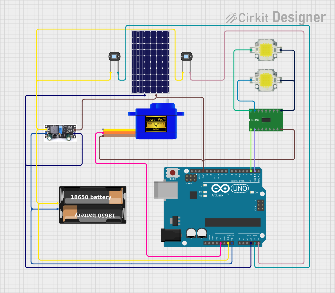
This circuit is a solar-powered control system with light detection and actuation capabilities. It uses a solar panel to charge a battery and an Arduino UNO to monitor light levels via photodiodes and control high-power LEDs and a servomotor through a Darlington Driver. The system's functionality is determined by the embedded code running on the Arduino.
Solar-Powered Battery Backup System with Automatic Transfer Switch

This circuit is a solar power management system that integrates a solar panel, battery, and inverter to provide a stable 12V DC and 220V AC output. It includes automatic transfer switches (ATS) and circuit breakers for safety and reliability, as well as a low voltage disconnect to protect the battery from deep discharge.
Arduino UNO Based Automated Solar-Powered Irrigation System with Soil Moisture Sensing
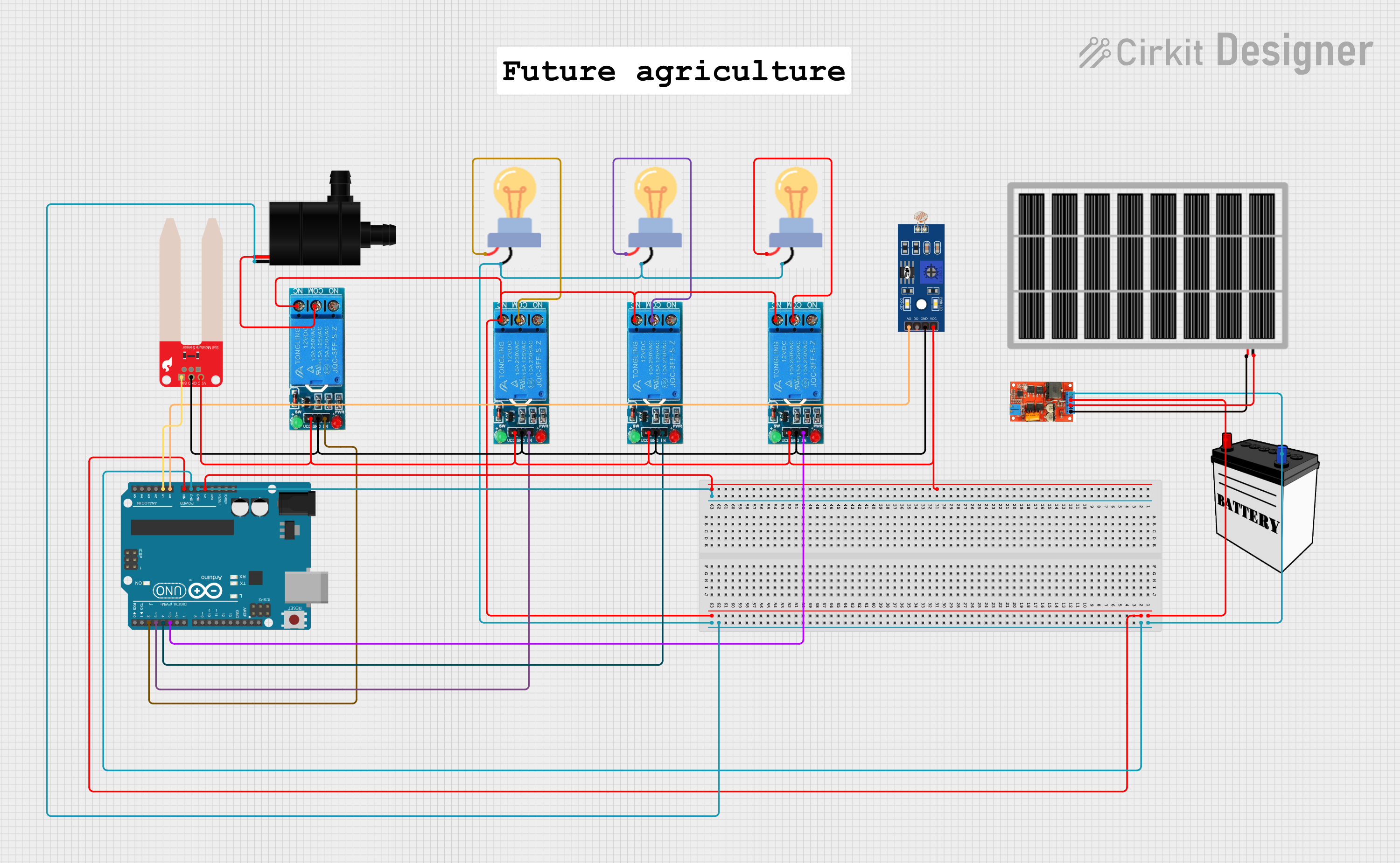
This is an autonomous environmental control system powered by a solar panel with battery backup, capable of monitoring light levels and soil moisture to control lighting and water pump operation through relays. The Arduino UNO serves as the central controller, reading sensor inputs and managing power to the bulbs and water pump based on environmental conditions.
Explore Projects Built with AUTOMATIC SOLAR
Solar-Powered Home Energy System with Automatic Transfer Switch and Battery Backup
This circuit is a solar power system with an automatic transfer switch (ATS) that manages power from both a solar panel and an AC supply. The solar panel charges a battery through a solar charge controller, and the power inverter converts the stored DC power to AC, which is then distributed through an MCB to a socket. The ATS ensures seamless switching between solar and AC power sources.
Solar-Powered LED Illumination System with Arduino Control
This circuit is a solar-powered control system with light detection and actuation capabilities. It uses a solar panel to charge a battery and an Arduino UNO to monitor light levels via photodiodes and control high-power LEDs and a servomotor through a Darlington Driver. The system's functionality is determined by the embedded code running on the Arduino.
Solar-Powered Battery Backup System with Automatic Transfer Switch
This circuit is a solar power management system that integrates a solar panel, battery, and inverter to provide a stable 12V DC and 220V AC output. It includes automatic transfer switches (ATS) and circuit breakers for safety and reliability, as well as a low voltage disconnect to protect the battery from deep discharge.
Arduino UNO Based Automated Solar-Powered Irrigation System with Soil Moisture Sensing
This is an autonomous environmental control system powered by a solar panel with battery backup, capable of monitoring light levels and soil moisture to control lighting and water pump operation through relays. The Arduino UNO serves as the central controller, reading sensor inputs and managing power to the bulbs and water pump based on environmental conditions.
Common Applications and Use Cases
- Residential and commercial solar panel installations
- Solar farms for renewable energy production
- Off-grid solar systems for remote areas
- Educational projects and research on solar energy optimization
Technical Specifications
Key Technical Details
- Operating Voltage: 12V DC
- Current Consumption: 1A (typical), 2A (peak)
- Motor Type: DC motor with gear reduction
- Control System: Microcontroller-based (compatible with Arduino, Raspberry Pi, etc.)
- Sensors: Light-dependent resistors (LDRs) for sunlight detection
- Tracking Accuracy: ±2 degrees
- Operating Temperature: -20°C to 60°C
- Panel Load Capacity: Up to 20 kg
Pin Configuration and Descriptions
| Pin Name | Type | Description |
|---|---|---|
| VCC | Power Input | Connect to a 12V DC power supply. |
| GND | Ground | Connect to the ground of the power supply and circuit. |
| LDR1 | Analog Input | Input from the first light-dependent resistor (used for sunlight detection). |
| LDR2 | Analog Input | Input from the second light-dependent resistor (used for sunlight detection). |
| MOTOR+ | Motor Output | Positive terminal of the motor for panel movement. |
| MOTOR- | Motor Output | Negative terminal of the motor for panel movement. |
| EN | Digital Input | Enable pin to activate or deactivate the tracking system. |
| DIR | Digital Input | Direction control pin for motor movement. |
Usage Instructions
How to Use the Component in a Circuit
- Power Supply: Connect the VCC pin to a 12V DC power source and the GND pin to the ground.
- Sensor Placement: Place the LDRs on opposite sides of the solar panel to detect sunlight intensity.
- Motor Connection: Connect the MOTOR+ and MOTOR- pins to the motor terminals for panel movement.
- Control Signals: Use a microcontroller (e.g., Arduino UNO) to send signals to the EN and DIR pins for enabling and controlling the motor's direction.
- Calibration: Adjust the sensitivity of the LDRs to ensure accurate sunlight tracking.
Important Considerations and Best Practices
- Ensure the motor's load capacity matches the weight of the solar panel.
- Protect the device from extreme weather conditions using a weatherproof enclosure.
- Use a diode across the motor terminals to prevent back EMF from damaging the circuit.
- Regularly clean the LDRs to maintain accurate sunlight detection.
- Test the system periodically to ensure proper alignment and functionality.
Example Code for Arduino UNO
// Automatic Solar Tracking System Code for Arduino UNO
// This code uses two LDRs to control the motor for solar panel alignment.

#define LDR1 A0  // LDR1 connected to analog pin A0
#define LDR2 A1  // LDR2 connected to analog pin A1
#define MOTOR_EN 9  // Motor enable pin connected to digital pin 9
#define MOTOR_DIR 8 // Motor direction pin connected to digital pin 8

void setup() {
  pinMode(MOTOR_EN, OUTPUT);  // Set motor enable pin as output
  pinMode(MOTOR_DIR, OUTPUT); // Set motor direction pin as output
  Serial.begin(9600);         // Initialize serial communication for debugging
}

void loop() {
  int ldr1Value = analogRead(LDR1); // Read value from LDR1
  int ldr2Value = analogRead(LDR2); // Read value from LDR2

  Serial.print("LDR1: "); // Print LDR1 value for debugging
  Serial.print(ldr1Value);
  Serial.print(" LDR2: "); // Print LDR2 value for debugging
  Serial.println(ldr2Value);

  if (ldr1Value > ldr2Value + 50) { // If LDR1 detects more light
    digitalWrite(MOTOR_DIR, HIGH);  // Set motor direction to one side
    analogWrite(MOTOR_EN, 150);     // Enable motor with moderate speed
  } else if (ldr2Value > ldr1Value + 50) { // If LDR2 detects more light
    digitalWrite(MOTOR_DIR, LOW);   // Set motor direction to the other side
    analogWrite(MOTOR_EN, 150);     // Enable motor with moderate speed
  } else {
    analogWrite(MOTOR_EN, 0);       // Stop the motor if light is balanced
  }

  delay(100); // Small delay for stability
}
Troubleshooting and FAQs
Common Issues and Solutions
Motor Not Moving:
- Check the power supply voltage and current rating.
- Ensure the motor connections (MOTOR+ and MOTOR-) are secure.
- Verify that the EN pin is receiving a HIGH signal.
Inaccurate Sunlight Tracking:
- Clean the LDRs to remove dust or debris.
- Recalibrate the LDR sensitivity in the code if necessary.
- Ensure the LDRs are positioned correctly on the solar panel.
Overheating of Components:
- Use a heat sink or cooling fan for the motor driver if it overheats.
- Check for excessive load on the motor and reduce the panel weight if needed.
No Response from the System:
- Verify all connections and ensure the microcontroller is powered on.
- Check the code for errors and re-upload it to the Arduino UNO.
FAQs
Can this device handle larger solar panels?
- Yes, but ensure the motor and mechanical structure are rated for the panel's weight.
Is it compatible with other microcontrollers?
- Yes, it can be used with other microcontrollers like Raspberry Pi, ESP32, etc., with minor modifications.
What happens during cloudy weather?
- The system will remain idle or make minor adjustments based on ambient light levels.
Can I use a battery as the power source?
- Yes, a 12V battery can be used, but ensure it has sufficient capacity to power the system.