Cirkit Designer
Your all-in-one circuit design IDE
Home /
Component Documentation
How to Use ESP32 NodeMCU Modul WiFi Entwicklungsboard mit CP2102: Examples, Pinouts, and Specs
Introduction
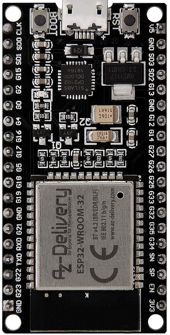
The ESP32 NodeMCU Module, manufactured by AZDelivery, is a versatile development board featuring the ESP32 microcontroller. This board is equipped with built-in WiFi and Bluetooth capabilities, making it ideal for a wide range of IoT (Internet of Things) applications. The CP2102 USB-to-UART bridge simplifies programming and debugging, providing a seamless development experience.
Explore Projects Built with ESP32 NodeMCU Modul WiFi Entwicklungsboard mit CP2102
ESP8266 NodeMCU with LoRa and RS-485 Communication and Ethernet Connectivity

This circuit serves as a multi-protocol communication hub featuring two ESP8266 NodeMCUs for processing, each connected to a LoRa Ra-02 SX1278 for long-range wireless communication. One NodeMCU is also connected to an RS-485 module for serial communication and a W5500 Ethernet module for network connectivity, with MB102 modules supplying power.
ESP8266 NodeMCU with LoRa and RS-485 Communication Interface

This circuit features two ESP8266 NodeMCU microcontrollers, each interfaced with a LoRa Ra-02 SX1278 module for long-range wireless communication, and an RS-485 module for wired serial communication. The ESP8266 microcontrollers are responsible for handling the communication protocols and data processing. Power is supplied to the microcontrollers via an MB102 Breadboard Power Supply Module, which provides both 3.3V and 5V outputs.
ESP32 and NRF24L01 Wireless Control Circuit
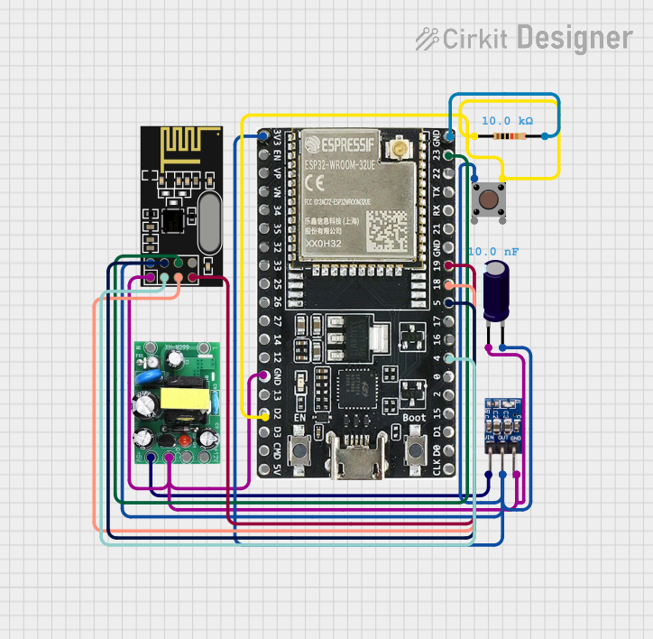
This circuit features an ESP32-WROOM-32UE microcontroller interfaced with an NRF24L01 wireless transceiver module, allowing for wireless communication capabilities. A pushbutton with a pull-down resistor is connected to the ESP32 for user input. Power regulation is managed by an AMS1117 3.3V regulator, which receives 5V from an AC-DC PSU board and is stabilized by an electrolytic capacitor, providing a stable 3.3V supply to the ESP32 and NRF24L01.
ESP32-Based GPS Tracker with SD Card Logging and Barometric Sensor

This circuit features an ESP32 Wroom Dev Kit as the main microcontroller, interfaced with an MPL3115A2 sensor for pressure and temperature readings, and a Neo 6M GPS module for location tracking. The ESP32 is also connected to an SD card reader for data logging purposes. A voltage regulator is used to step down the USB power supply to 3.3V, which powers the ESP32, the sensor, and the SD card reader.
Explore Projects Built with ESP32 NodeMCU Modul WiFi Entwicklungsboard mit CP2102
ESP8266 NodeMCU with LoRa and RS-485 Communication and Ethernet Connectivity
This circuit serves as a multi-protocol communication hub featuring two ESP8266 NodeMCUs for processing, each connected to a LoRa Ra-02 SX1278 for long-range wireless communication. One NodeMCU is also connected to an RS-485 module for serial communication and a W5500 Ethernet module for network connectivity, with MB102 modules supplying power.
ESP8266 NodeMCU with LoRa and RS-485 Communication Interface
This circuit features two ESP8266 NodeMCU microcontrollers, each interfaced with a LoRa Ra-02 SX1278 module for long-range wireless communication, and an RS-485 module for wired serial communication. The ESP8266 microcontrollers are responsible for handling the communication protocols and data processing. Power is supplied to the microcontrollers via an MB102 Breadboard Power Supply Module, which provides both 3.3V and 5V outputs.
ESP32 and NRF24L01 Wireless Control Circuit
This circuit features an ESP32-WROOM-32UE microcontroller interfaced with an NRF24L01 wireless transceiver module, allowing for wireless communication capabilities. A pushbutton with a pull-down resistor is connected to the ESP32 for user input. Power regulation is managed by an AMS1117 3.3V regulator, which receives 5V from an AC-DC PSU board and is stabilized by an electrolytic capacitor, providing a stable 3.3V supply to the ESP32 and NRF24L01.
ESP32-Based GPS Tracker with SD Card Logging and Barometric Sensor
This circuit features an ESP32 Wroom Dev Kit as the main microcontroller, interfaced with an MPL3115A2 sensor for pressure and temperature readings, and a Neo 6M GPS module for location tracking. The ESP32 is also connected to an SD card reader for data logging purposes. A voltage regulator is used to step down the USB power supply to 3.3V, which powers the ESP32, the sensor, and the SD card reader.
Common Applications and Use Cases
- Home Automation: Control and monitor home appliances remotely.
- IoT Projects: Collect and transmit sensor data over WiFi or Bluetooth.
- Wearable Devices: Develop smart wearable gadgets with wireless connectivity.
- Robotics: Implement wireless control and communication in robotic systems.
- Prototyping: Rapidly prototype and test new ideas with easy-to-use development tools.
Technical Specifications
Key Technical Details
| Specification | Value |
|---|---|
| Microcontroller | ESP32 |
| Operating Voltage | 3.3V |
| Input Voltage | 5V (via USB) |
| Digital I/O Pins | 34 |
| Analog Input Pins | 18 (ADC) |
| Flash Memory | 4MB |
| SRAM | 520KB |
| WiFi Standard | 802.11 b/g/n |
| Bluetooth Standard | Bluetooth v4.2 BR/EDR and BLE |
| USB-to-UART Bridge | CP2102 |
| Dimensions | 58mm x 31mm x 13mm |
Pin Configuration and Descriptions
| Pin Number | Pin Name | Description |
|---|---|---|
| 1 | EN | Enable pin (active high) |
| 2 | IO23 | GPIO23, SPI MOSI |
| 3 | IO22 | GPIO22, I2C SCL |
| 4 | TXD0 | UART0 TXD |
| 5 | RXD0 | UART0 RXD |
| 6 | IO21 | GPIO21, I2C SDA |
| 7 | GND | Ground |
| 8 | IO19 | GPIO19, SPI MISO |
| 9 | IO18 | GPIO18, SPI SCK |
| 10 | IO17 | GPIO17, UART2 TXD |
| 11 | IO16 | GPIO16, UART2 RXD |
| 12 | IO15 | GPIO15, HSPI CS |
| 13 | IO14 | GPIO14, HSPI CLK |
| 14 | IO13 | GPIO13, HSPI MOSI |
| 15 | IO12 | GPIO12, HSPI MISO |
| 16 | IO11 | GPIO11, SPI CS |
| 17 | IO10 | GPIO10 |
| 18 | IO9 | GPIO9 |
| 19 | IO8 | GPIO8 |
| 20 | IO7 | GPIO7 |
| 21 | IO6 | GPIO6 |
| 22 | IO5 | GPIO5, HSPI CLK |
| 23 | IO4 | GPIO4 |
| 24 | IO3 | GPIO3, UART0 RXD |
| 25 | IO2 | GPIO2, HSPI MISO |
| 26 | IO1 | GPIO1, UART0 TXD |
| 27 | IO0 | GPIO0, Boot Mode Select |
| 28 | 3V3 | 3.3V Power Output |
| 29 | GND | Ground |
| 30 | VIN | 5V Power Input |
Usage Instructions
How to Use the Component in a Circuit
Powering the Board:
- Connect the board to your computer using a USB cable. This will provide power and enable programming via the CP2102 USB-to-UART bridge.
Programming the ESP32:
- Install the necessary drivers for the CP2102 USB-to-UART bridge.
- Use the Arduino IDE or another compatible development environment to write and upload code to the ESP32.
Connecting Peripherals:
- Use the GPIO pins to connect sensors, actuators, and other peripherals.
- Ensure that the peripherals operate at 3.3V logic levels to avoid damaging the ESP32.
Important Considerations and Best Practices
- Voltage Levels: The ESP32 operates at 3.3V. Ensure that any connected peripherals are compatible with 3.3V logic levels.
- Power Supply: When using power-hungry peripherals, consider providing an external 3.3V power supply to avoid overloading the USB port.
- Pin Multiplexing: Some pins have multiple functions (e.g., GPIO, ADC, UART). Refer to the ESP32 datasheet to avoid conflicts.
- WiFi and Bluetooth: Ensure that your code properly initializes and manages WiFi and Bluetooth connections to avoid interference and connectivity issues.
Example Code for Arduino IDE
#include <WiFi.h>

// Replace with your network credentials
const char* ssid = "your_SSID";
const char* password = "your_PASSWORD";

void setup() {
  // Initialize serial communication
  Serial.begin(115200);

  // Connect to Wi-Fi
  WiFi.begin(ssid, password);

  // Wait for connection
  while (WiFi.status() != WL_CONNECTED) {
    delay(1000);
    Serial.println("Connecting to WiFi...");
  }

  // Print the IP address
  Serial.println("Connected to WiFi");
  Serial.print("IP Address: ");
  Serial.println(WiFi.localIP());
}

void loop() {
  // Your main code here
}
Troubleshooting and FAQs
Common Issues Users Might Face
Unable to Connect to WiFi:
- Solution: Double-check the SSID and password. Ensure that the WiFi network is within range and not experiencing issues.
ESP32 Not Detected by Computer:
- Solution: Ensure that the CP2102 drivers are correctly installed. Try using a different USB cable or port.
Program Upload Fails:
- Solution: Press and hold the "BOOT" button on the ESP32 while uploading the code. Release the button once the upload starts.
Peripheral Not Working:
- Solution: Verify the wiring and ensure that the peripheral operates at 3.3V logic levels. Check the pin configuration in your code.
Solutions and Tips for Troubleshooting
- Serial Monitor: Use the Serial Monitor in the Arduino IDE to print debug messages and monitor the status of your code.
- Power Supply: Ensure that the ESP32 and connected peripherals have a stable power supply. Use an external power source if necessary.
- Firmware Updates: Keep the ESP32 firmware and development environment up to date to benefit from the latest features and bug fixes.
By following this documentation, users can effectively utilize the ESP32 NodeMCU Module for a variety of applications, from simple projects to complex IoT systems.