
How to Use lm2956: Examples, Pinouts, and Specs
 Design with lm2956 in Cirkit Designer
Introduction
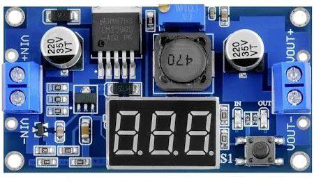
The LM2956 is a low-dropout (LDO) voltage regulator designed to deliver a stable and regulated output voltage with a minimal input-to-output voltage difference. Manufactured as part of the "Step Down" series, this component is ideal for applications requiring efficient power regulation and excellent thermal performance. Its compact design and high efficiency make it suitable for battery-powered devices, embedded systems, and other power-sensitive applications.
Explore Projects Built with lm2956
 Open Project in Cirkit Designer
 Open Project in Cirkit Designer
 Open Project in Cirkit Designer
 Open Project in Cirkit Designer
Explore Projects Built with lm2956
Open Project in Cirkit DesignerOpen Project in Cirkit DesignerOpen Project in Cirkit DesignerOpen Project in Cirkit DesignerCommon Applications
- Power supply regulation for microcontrollers and digital circuits
- Battery-powered devices
- Portable electronics
- Industrial automation systems
- Embedded systems requiring low-noise power supplies
Technical Specifications
Key Technical Details
| Parameter | Value |
|---|---|
| Input Voltage Range | 4.5V to 40V |
| Output Voltage Range | Adjustable (1.23V to 37V) |
| Maximum Output Current | 3A |
| Dropout Voltage | 0.5V (typical at 3A load) |
| Efficiency | Up to 90% (depending on load) |
| Operating Temperature | -40°C to +125°C |
| Package Type | TO-220, TO-263, or SOT-223 |
Pin Configuration and Descriptions
The LM2956 typically comes in a 3-pin package. Below is the pinout description:
| Pin Number | Pin Name | Description |
|---|---|---|
| 1 | Input (VIN) | Input voltage pin. Connect to the unregulated DC |
| input source. | ||
| 2 | Ground (GND) | Ground pin. Connect to the circuit ground. |
| 3 | Output (VOUT) | Regulated output voltage pin. Connect to the |
| load circuit. |
Usage Instructions
How to Use the LM2956 in a Circuit
- Input Voltage: Ensure the input voltage (VIN) is within the specified range (4.5V to 40V) and at least 0.5V higher than the desired output voltage.
- Output Voltage Adjustment: If using the adjustable version, connect a resistor divider network to set the desired output voltage. Refer to the formula: [ V_{OUT} = V_{REF} \times \left(1 + \frac{R_2}{R_1}\right) ] where ( V_{REF} ) is typically 1.23V.
- Capacitors: Place a suitable input capacitor (e.g., 10µF) close to the VIN pin to stabilize the input voltage. Similarly, use an output capacitor (e.g., 22µF) to ensure stable operation and reduce noise.
- Thermal Management: If operating at high currents, attach a heatsink to the LM2956 to dissipate heat and maintain safe operating temperatures.
Example Circuit
Below is an example of using the LM2956 to regulate a 12V input to a 5V output:
   +12V ----+----[CIN]----+----> LM2956 (VIN)
            |             |
           GND           GND
                        (VOUT)----[COUT]----+----> +5V
                                           |
                                          GND
Arduino UNO Example Code
The LM2956 can be used to power an Arduino UNO by regulating a higher voltage (e.g., 12V) down to 5V. Connect the LM2956 output to the Arduino's 5V pin.
// Example: Blink an LED using Arduino UNO powered by LM2956
// Ensure the LM2956 output is connected to the Arduino's 5V pin.

int ledPin = 13; // Pin connected to the onboard LED

void setup() {
  pinMode(ledPin, OUTPUT); // Set the LED pin as an output
}

void loop() {
  digitalWrite(ledPin, HIGH); // Turn the LED on
  delay(1000);                // Wait for 1 second
  digitalWrite(ledPin, LOW);  // Turn the LED off
  delay(1000);                // Wait for 1 second
}
Troubleshooting and FAQs
Common Issues and Solutions
No Output Voltage:
- Cause: Input voltage is too low or not connected.
- Solution: Verify that the input voltage is within the specified range and properly connected.
Output Voltage is Incorrect:
- Cause: Incorrect resistor values in the voltage divider (for adjustable versions).
- Solution: Recalculate and verify the resistor values using the output voltage formula.
Overheating:
- Cause: Excessive current draw or insufficient heat dissipation.
- Solution: Attach a heatsink to the LM2956 and ensure proper ventilation.
Noise or Instability:
- Cause: Missing or insufficient input/output capacitors.
- Solution: Add capacitors as recommended in the datasheet (e.g., 10µF on VIN and 22µF on VOUT).
FAQs
Q1: Can the LM2956 be used with a 3.3V output?
A1: Yes, the LM2956 can be configured for a 3.3V output by selecting the appropriate resistor values in the voltage divider network.
Q2: What is the maximum current the LM2956 can handle?
A2: The LM2956 can handle up to 3A of output current, provided adequate thermal management is in place.
Q3: Can I use the LM2956 without a heatsink?
A3: For low current applications (e.g., <1A), a heatsink may not be necessary. However, for higher currents, a heatsink is recommended to prevent overheating.
Q4: Is the LM2956 suitable for powering sensitive analog circuits?
A4: Yes, the LM2956 provides low-noise output, making it suitable for sensitive analog and digital circuits.
This concludes the documentation for the LM2956. For further details, refer to the manufacturer's datasheet.