How to Use Voltage Sensor DC 25V: Examples, Pinouts, and Specs
Introduction
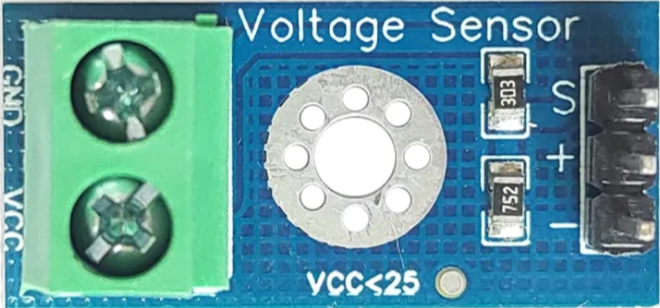
The Voltage Sensor DC 25V is an electronic component designed to measure DC voltage levels up to 25 volts. It is commonly used in various applications such as battery monitoring, solar panel voltage measurement, and in any system where voltage level monitoring is crucial. This sensor is particularly useful in microcontroller-based projects, where it can be interfaced with platforms like Arduino to read and process voltage levels in real-time.
Explore Projects Built with Voltage Sensor DC 25V
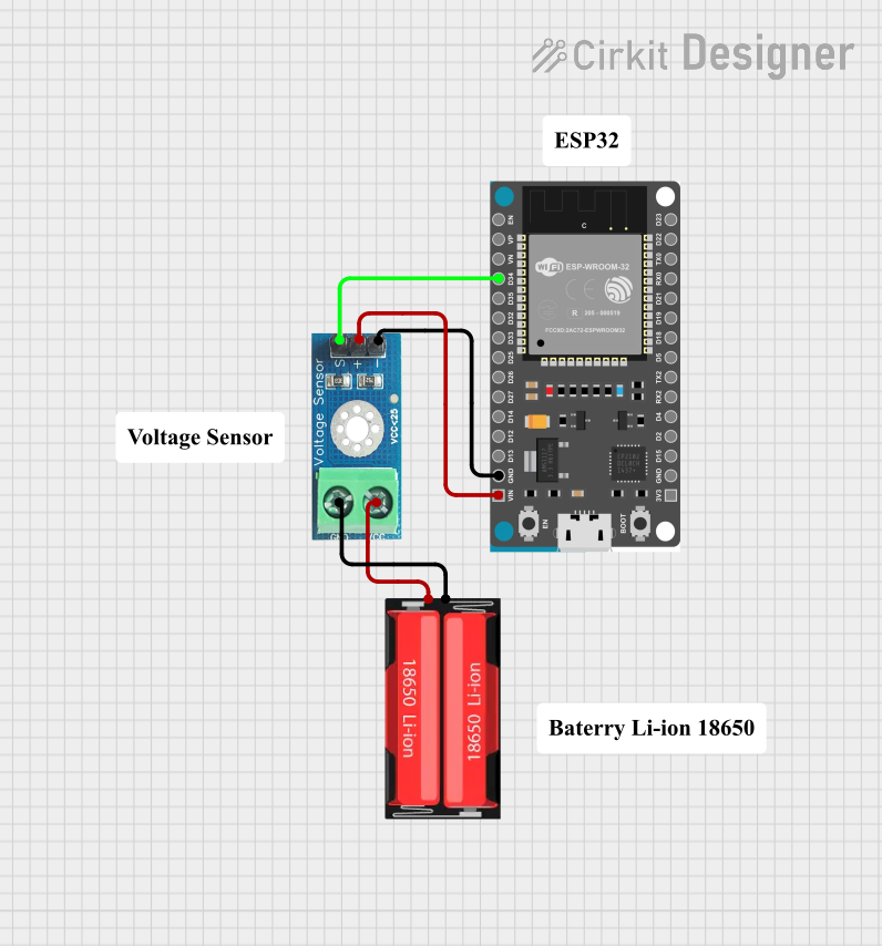
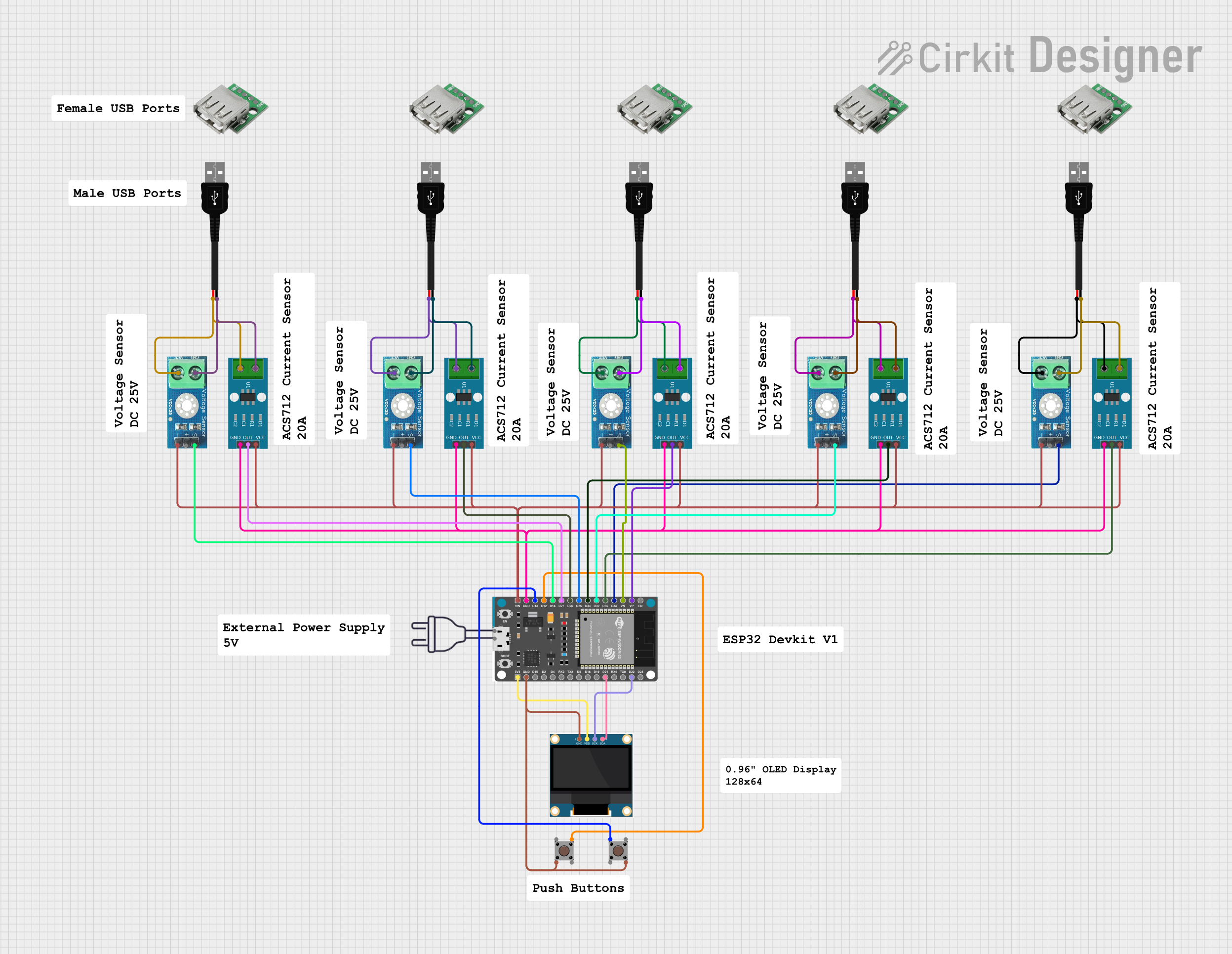
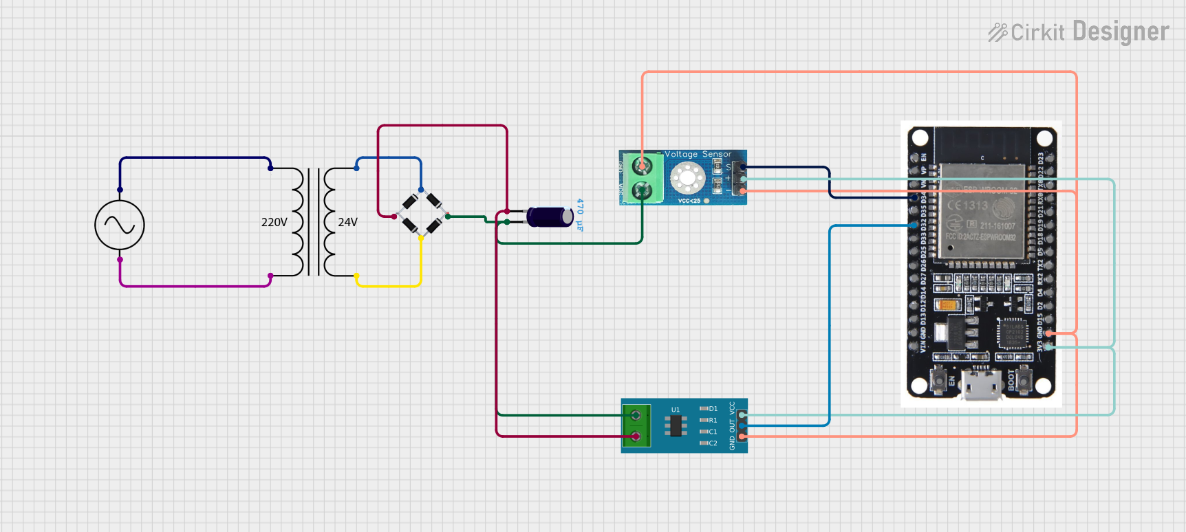
Explore Projects Built with Voltage Sensor DC 25V
Technical Specifications
Key Technical Details
- Input Voltage (Vin): 0 to 25V DC
- Output Voltage (Vout): 0 to 5V DC (scaled output)
- Sensitivity: Typically 0.1V/A for easy reading by ADC
- Accuracy: ±2%
- Operating Temperature: -40°C to +85°C
- Dimensions: Varies by manufacturer
Pin Configuration and Descriptions
| Pin Number | Name | Description |
|---|---|---|
| 1 | VCC | Connect to 5V power supply |
| 2 | GND | Connect to ground |
| 3 | VOUT | Analog voltage output |
Usage Instructions
Interfacing with a Circuit
- Connect the VCC pin to a 5V power supply.
- Connect the GND pin to the ground of the power supply.
- Connect the VOUT pin to an analog input pin on your microcontroller (e.g., A0 on an Arduino UNO).
Important Considerations and Best Practices
- Ensure that the input voltage does not exceed 25V to prevent damage to the sensor.
- Use a voltage divider or level shifter if your microcontroller operates at a voltage level other than 5V.
- Calibrate the sensor if precise measurements are required, as there may be slight variances between units.
- Avoid placing the sensor in environments with extreme temperatures or humidity.
Example Code for Arduino UNO
// Define the analog input pin connected to the sensor
const int analogInPin = A0;

void setup() {
  // Initialize serial communication at 9600 bits per second:
  Serial.begin(9600);
}

void loop() {
  // Read the value from the sensor
  int sensorValue = analogRead(analogInPin);
  // Convert the analog reading to voltage
  float voltage = sensorValue * (5.0 / 1023.0) * (25.0 / 5.0);

  // Print out the voltage
  Serial.print("Voltage: ");
  Serial.println(voltage);

  // Wait for a bit to avoid spamming the serial output
  delay(1000);
}
Troubleshooting and FAQs
Common Issues
- Inaccurate Readings: Ensure that the sensor is correctly calibrated and that the input voltage does not exceed 25V.
- No Output: Check all connections, ensure that the VCC and GND are properly connected, and that the microcontroller is functioning correctly.
- Sensor Overheating: Disconnect immediately if the sensor is overheating, and verify that the input voltage is within the specified range.
Solutions and Tips for Troubleshooting
- Calibration: Use a known voltage source to calibrate the sensor output.
- Connection Check: Use a multimeter to verify that all connections are secure and that there is continuity where expected.
- Sensor Replacement: If the sensor is damaged or continues to operate outside of its specifications, consider replacing it.
FAQs
Q: Can I measure voltages higher than 25V with this sensor? A: No, applying more than 25V to the sensor can damage it. Use a voltage divider to measure higher voltages.
Q: How can I improve the accuracy of the sensor? A: Calibration with a known voltage source and averaging multiple readings can improve accuracy.
Q: Is it possible to use this sensor with a 3.3V microcontroller? A: Yes, but you will need to use a level shifter or voltage divider to ensure the output voltage is within the microcontroller's input voltage range.
Remember to always follow safety precautions when working with electrical components and circuits to prevent injury or damage to your equipment.