How to Use ESP32 PCB: Examples, Pinouts, and Specs
Introduction
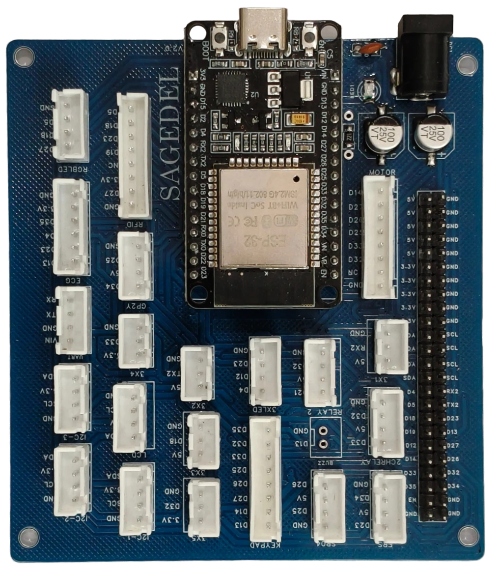
The ESP32 PCB (SAGEDEL V2.0) is a printed circuit board that integrates the ESP32 microcontroller, a powerful dual-core processor with built-in Wi-Fi and Bluetooth capabilities. This PCB is designed to simplify the development of IoT (Internet of Things) applications, embedded systems, and wireless communication projects. With its compact design and versatile connectivity options, the ESP32 PCB is suitable for a wide range of applications, including smart home devices, wearable electronics, and industrial automation.
Explore Projects Built with ESP32 PCB


Explore Projects Built with ESP32 PCB
Common Applications
- IoT devices and smart home systems
- Wireless sensor networks
- Wearable technology
- Robotics and automation
- Data logging and remote monitoring
- Prototyping and educational projects
Technical Specifications
The following table outlines the key technical details of the ESP32 PCB (SAGEDEL V2.0):
| Specification | Details |
|---|---|
| Microcontroller | ESP32 (dual-core, 32-bit Xtensa LX6 processor) |
| Clock Speed | Up to 240 MHz |
| Flash Memory | 4 MB (default) |
| SRAM | 520 KB |
| Wireless Connectivity | Wi-Fi 802.11 b/g/n, Bluetooth v4.2 + BLE |
| Operating Voltage | 3.3V |
| Input Voltage Range | 5V (via USB) or 7-12V (via VIN pin) |
| GPIO Pins | 30 (multipurpose, including ADC, DAC, PWM, I2C, SPI, UART) |
| ADC Channels | 18 (12-bit resolution) |
| DAC Channels | 2 |
| Power Consumption | 160 mA (average during operation) |
| Dimensions | 25 mm x 50 mm |
| Manufacturer | SAGEDEL |
| Part ID | V2.0 |
Pin Configuration
The ESP32 PCB features a standard pinout for easy integration into projects. Below is the pin configuration:
| Pin Name | Function | Description |
|---|---|---|
| VIN | Power Input | Accepts 7-12V input for powering the board. |
| GND | Ground | Common ground for the circuit. |
| 3V3 | Power Output | Provides 3.3V output for external components. |
| EN | Enable | Enables or disables the ESP32 chip. |
| GPIO0 | General Purpose I/O | Can be used for input, output, or boot mode selection. |
| GPIO2 | General Purpose I/O | Multipurpose pin, often used for onboard LED. |
| TXD0 | UART Transmit | UART0 transmit pin for serial communication. |
| RXD0 | UART Receive | UART0 receive pin for serial communication. |
| SDA | I2C Data | Data line for I2C communication. |
| SCL | I2C Clock | Clock line for I2C communication. |
| MOSI | SPI Master Out, Slave In | SPI data output from master to slave. |
| MISO | SPI Master In, Slave Out | SPI data input from slave to master. |
| SCK | SPI Clock | Clock line for SPI communication. |
| A0-A17 | Analog Input | 12-bit ADC channels for analog signal input. |
| DAC1, DAC2 | Digital-to-Analog Converter | Outputs analog signals (8-bit resolution). |
Usage Instructions
How to Use the ESP32 PCB in a Circuit
Powering the Board:
- Use a USB cable to supply 5V via the micro-USB port.
- Alternatively, connect a 7-12V power source to the VIN pin.
- Ensure the GND pin is connected to the common ground of your circuit.
Programming the ESP32:
- Install the ESP32 board package in the Arduino IDE or use the ESP-IDF framework.
- Connect the ESP32 PCB to your computer via USB.
- Select the correct board and port in the IDE, then upload your code.
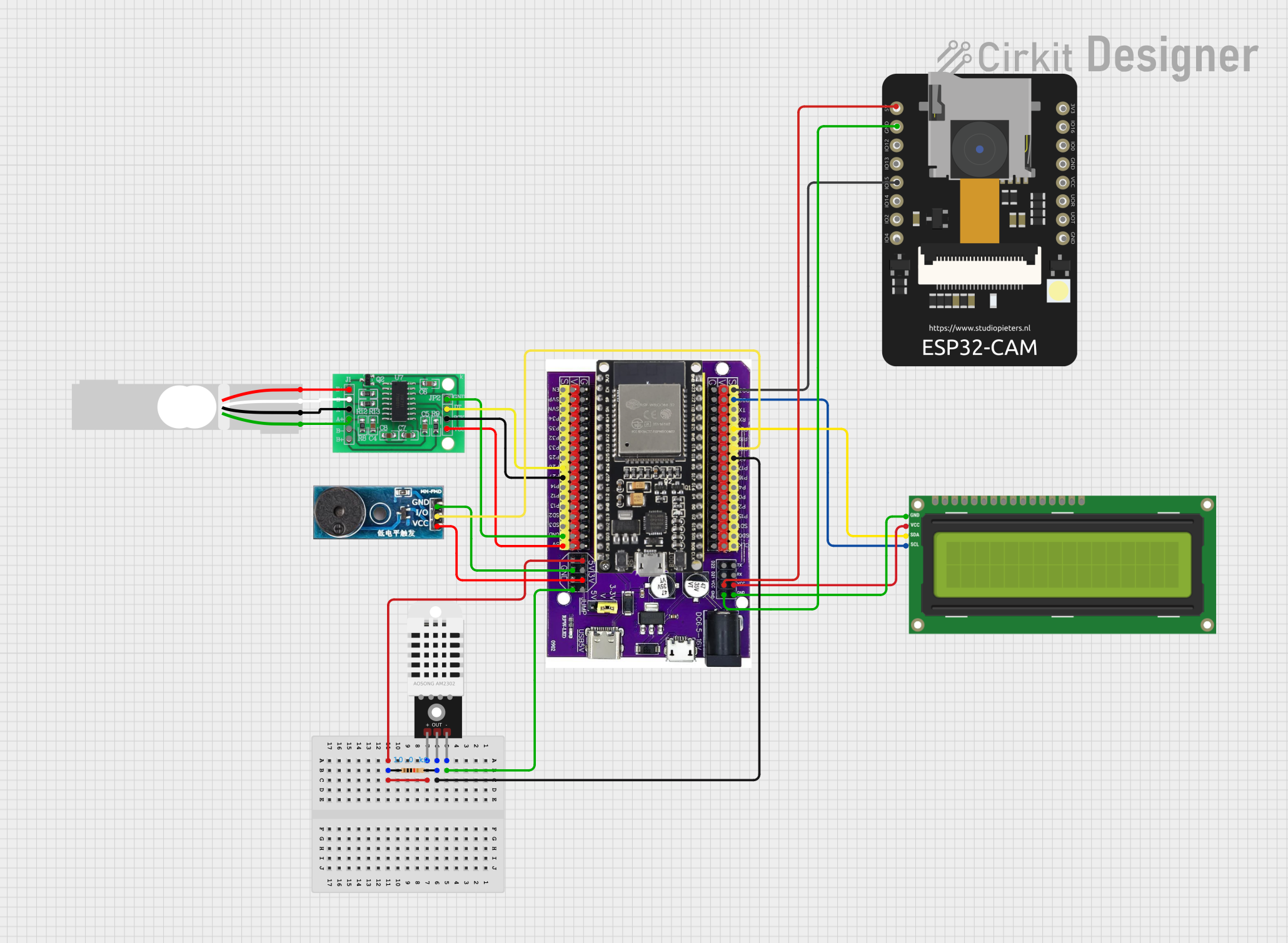
Connecting Peripherals:
- Use GPIO pins for digital input/output, PWM, or communication protocols (I2C, SPI, UART).
- For analog input, connect sensors to the ADC pins (A0-A17).
- For analog output, use DAC1 or DAC2 pins.
Wireless Connectivity:
- Configure Wi-Fi or Bluetooth settings in your code to enable wireless communication.
- Use the ESP32's built-in libraries for seamless integration.
Important Considerations
- Voltage Levels: Ensure all connected peripherals operate at 3.3V logic levels to avoid damaging the ESP32.
- Boot Mode: To enter boot mode for programming, hold down the BOOT button while pressing the EN button.
- Heat Management: The ESP32 may heat up during operation. Ensure proper ventilation or use a heatsink if necessary.
- Pin Multiplexing: Many GPIO pins have multiple functions. Refer to the ESP32 datasheet to avoid conflicts.
Example Code for Arduino UNO Integration
Below is an example of using the ESP32 PCB to connect to a Wi-Fi network and send data to a server:
#include <WiFi.h> // Include the Wi-Fi library

// Replace with your network credentials
const char* ssid = "Your_SSID";
const char* password = "Your_PASSWORD";

void setup() {
  Serial.begin(115200); // Initialize serial communication at 115200 baud
  delay(1000);

  // Connect to Wi-Fi
  Serial.print("Connecting to Wi-Fi");
  WiFi.begin(ssid, password);
  while (WiFi.status() != WL_CONNECTED) {
    delay(500);
    Serial.print(".");
  }
  Serial.println("\nWi-Fi connected!");
  Serial.print("IP Address: ");
  Serial.println(WiFi.localIP()); // Print the ESP32's IP address
}

void loop() {
  // Add your main code here
}
Troubleshooting and FAQs
Common Issues
ESP32 Not Detected by Computer:
- Ensure the USB cable is functional and supports data transfer.
- Install the correct USB-to-serial driver for your operating system.
Wi-Fi Connection Fails:
- Double-check the SSID and password in your code.
- Ensure the Wi-Fi network is within range and not overloaded.
Program Upload Fails:
- Verify the correct board and port are selected in the IDE.
- Hold the BOOT button while uploading the code to force the ESP32 into boot mode.
Overheating:
- Avoid overloading the GPIO pins with excessive current.
- Use a heatsink or fan if the ESP32 operates in a high-temperature environment.
FAQs
Q: Can I power the ESP32 PCB with a battery?
A: Yes, you can use a 3.7V LiPo battery connected to the 3V3 pin or a higher voltage battery (7-12V) connected to the VIN pin.Q: How many devices can the ESP32 connect to via Bluetooth?
A: The ESP32 supports up to 7 simultaneous Bluetooth connections in classic mode.Q: Can I use the ESP32 PCB with a 5V logic device?
A: No, the ESP32 operates at 3.3V logic levels. Use a level shifter to interface with 5V devices.Q: What is the maximum Wi-Fi range of the ESP32?
A: The range depends on the environment but typically extends up to 50 meters indoors and 200 meters outdoors.