How to Use LSM6DS3+LIS3MDL: Examples, Pinouts, and Specs
Introduction
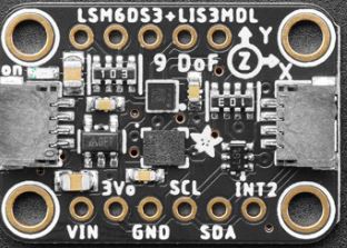
The LSM6DS3+LIS3MDL module is a compact, high-performance 9 degrees of freedom (9DOF) motion tracking system that combines a 3D digital accelerometer and a 3D digital gyroscope (LSM6DS3) with a 3D digital magnetometer (LIS3MDL). This sensor module is ideal for applications in robotics, drones, wearable devices, and other projects requiring precise motion tracking and orientation data.
Explore Projects Built with LSM6DS3+LIS3MDL
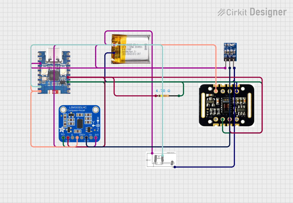


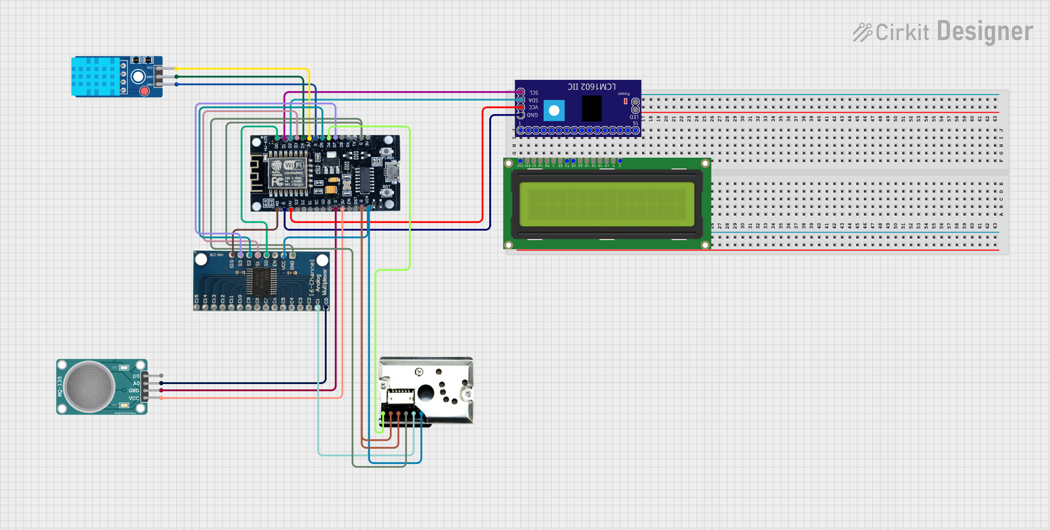
Explore Projects Built with LSM6DS3+LIS3MDL
Common Applications and Use Cases
- Robotics: For balance control and motion sensing.
- Drones: For flight stabilization and navigation.
- Wearable Devices: For activity tracking and gesture recognition.
- Virtual Reality (VR): For head tracking and motion sensing.
- Smartphones and Tablets: For orientation and step detection.
Technical Specifications
LSM6DS3 (Accelerometer and Gyroscope)
| Parameter | Specification |
|---|---|
| Supply Voltage | 1.71 V to 3.6 V |
| Accelerometer Range | ±2/±4/±8/±16 g |
| Gyroscope Range | ±125/±245/±500/±1000/±2000 dps |
| Output Data Rates (ODR) | Up to 6.66 kHz (gyro) and 1.66 kHz (accel) |
| Interface | I2C/SPI |
LIS3MDL (Magnetometer)
| Parameter | Specification |
|---|---|
| Supply Voltage | 2.5 V to 5.5 V |
| Magnetic Range | ±4/±8/±12/±16 gauss |
| Output Data Rates (ODR) | Up to 155 Hz |
| Interface | I2C/SPI |
Pin Configuration and Descriptions
| Pin Number | Name | Description |
|---|---|---|
| 1 | VDD | Power supply voltage |
| 2 | GND | Ground |
| 3 | SCL | I2C clock / SPI serial clock |
| 4 | SDA | I2C data / SPI serial data in (SDI) |
| 5 | SA0 | I2C address selection / SPI data out (SDO) |
| 6 | CS | SPI chip select (active low) |
| 7 | INT1 | LSM6DS3 interrupt 1 |
| 8 | INT2 | LSM6DS3 interrupt 2 |
| 9 | DRDY | LIS3MDL data ready output |
Usage Instructions
Integration into a Circuit
- Powering the Module: Connect the VDD pin to a power supply within the specified voltage range and GND to the common ground.
- Communication: For I2C communication, connect SCL to the I2C clock and SDA to the I2C data lines. For SPI, connect SCL, SDA, SA0, and CS as per SPI protocol.
- Interrupts: The INT1 and INT2 pins can be connected to microcontroller interrupt pins for motion detection and other interrupt-driven features.
- Data Ready: The DRDY pin can be used to signal when new data is available from the magnetometer.
Best Practices
- Use pull-up resistors on the I2C lines (SCL and SDA) if they are not already present on the microcontroller board.
- Keep the power supply stable and within the specified range to prevent damage to the module.
- Place the sensor away from magnetic fields that may interfere with the magnetometer readings.
Example Code for Arduino UNO
#include <Wire.h>
#include "LSM6DS3.h"
#include "LIS3MDL.h"

LSM6DS3 myIMU; // Accelerometer and gyroscope
LIS3MDL myMAG; // Magnetometer

void setup() {
  Wire.begin();
  Serial.begin(9600);

  // Initialize the LSM6DS3
  if (myIMU.begin() != 0) {
    Serial.println("Failed to initialize LSM6DS3!");
  } else {
    Serial.println("LSM6DS3 initialized successfully.");
  }

  // Initialize the LIS3MDL
  if (myMAG.begin() != 0) {
    Serial.println("Failed to initialize LIS3MDL!");
  } else {
    Serial.println("LIS3MDL initialized successfully.");
  }
}

void loop() {
  // Read accelerometer and gyroscope
  float accelX = myIMU.readFloatAccelX();
  float accelY = myIMU.readFloatAccelY();
  float accelZ = myIMU.readFloatAccelZ();
  float gyroX = myIMU.readFloatGyroX();
  float gyroY = myIMU.readFloatGyroY();
  float gyroZ = myIMU.readFloatGyroZ();

  // Read magnetometer
  float magX = myMAG.readFloatMagX();
  float magY = myMAG.readFloatMagY();
  float magZ = myMAG.readFloatMagZ();

  // Print the values
  Serial.print("Accel X: "); Serial.print(accelX); Serial.print(" ");
  Serial.print("Accel Y: "); Serial.print(accelY); Serial.print(" ");
  Serial.print("Accel Z: "); Serial.println(accelZ);

  Serial.print("Gyro X: "); Serial.print(gyroX); Serial.print(" ");
  Serial.print("Gyro Y: "); Serial.print(gyroY); Serial.print(" ");
  Serial.print("Gyro Z: "); Serial.println(gyroZ);

  Serial.print("Mag X: "); Serial.print(magX); Serial.print(" ");
  Serial.print("Mag Y: "); Serial.print(magY); Serial.print(" ");
  Serial.print("Mag Z: "); Serial.println(magZ);

  delay(1000); // Update every second
}
Troubleshooting and FAQs
Common Issues
- Sensor Not Responding: Ensure that the power supply is within the specified range and that the I2C/SPI connections are correct.
- Inaccurate Readings: Check for any magnetic interference near the magnetometer and calibrate the sensor if necessary.
- Interrupts Not Working: Verify the interrupt pins are correctly connected and configured in your microcontroller code.
FAQs
Q: Can I use this module with a 5V microcontroller like Arduino UNO? A: Yes, but ensure that the voltage levels on the I2C/SPI lines are compatible. Use level shifters if necessary.
Q: How do I calibrate the magnetometer? A: Calibration typically involves rotating the sensor in various orientations and using the collected data to adjust the readings.
Q: What is the default I2C address of the module? A: The LSM6DS3 has a default I2C address of 0x6A or 0x6B (depending on SA0), and the LIS3MDL has a default I2C address of 0x1C or 0x1E (also depending on SA0).
Q: How can I change the data rate of the sensors? A: The data rate can be changed through the sensor's registers. Refer to the datasheets for the specific register settings.
For further assistance, consult the datasheets of LSM6DS3 and LIS3MDL, or contact technical support.