
How to Use TC4427CPA: Examples, Pinouts, and Specs
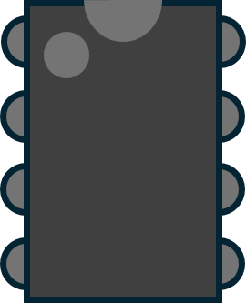
 Design with TC4427CPA in Cirkit Designer
Introduction
The TC4427CPA is a dual high-speed CMOS buffer/driver manufactured by Microchip Technology. It is designed to drive capacitive loads and interface with digital circuits. This component is capable of delivering high output current and operates over a wide supply voltage range, making it versatile for various applications.
Explore Projects Built with TC4427CPA
 Open Project in Cirkit Designer
 Open Project in Cirkit Designer
 Open Project in Cirkit Designer
 Open Project in Cirkit Designer
Explore Projects Built with TC4427CPA
Open Project in Cirkit DesignerOpen Project in Cirkit DesignerOpen Project in Cirkit DesignerOpen Project in Cirkit DesignerCommon Applications and Use Cases
- Driving MOSFETs and IGBTs in power electronics
- Signal buffering in digital circuits
- Pulse generation and signal conditioning
- Motor control and power management systems
- Applications requiring high-speed switching
Technical Specifications
The following table outlines the key technical specifications of the TC4427CPA:
| Parameter | Value |
|---|---|
| Supply Voltage (VDD) | 4.5V to 18V |
| Output Current (Peak) | ±1.5A |
| Input Voltage Range | 0V to VDD |
| Propagation Delay | 30ns (typical) |
| Rise/Fall Time | 25ns (typical) |
| Operating Temperature Range | -40°C to +85°C |
| Package Type | 8-pin PDIP (Plastic Dual In-line) |
Pin Configuration and Descriptions
The TC4427CPA is an 8-pin device. The pinout and descriptions are as follows:
| Pin Number | Pin Name | Description |
|---|---|---|
| 1 | IN A | Input signal for Channel A |
| 2 | GND | Ground connection |
| 3 | IN B | Input signal for Channel B |
| 4 | OUT B | Output signal for Channel B |
| 5 | VDD | Positive supply voltage |
| 6 | OUT A | Output signal for Channel A |
| 7 | NC | No connection (leave unconnected or grounded for stability) |
| 8 | NC | No connection (leave unconnected or grounded for stability) |
Usage Instructions
How to Use the TC4427CPA in a Circuit
- Power Supply: Connect the VDD pin to a stable power supply within the range of 4.5V to 18V. Connect the GND pin to the circuit ground.
- Input Signals: Apply logic-level signals (0V to VDD) to the IN A and IN B pins. These signals will control the corresponding outputs (OUT A and OUT B).
- Output Load: Connect the desired load (e.g., MOSFET gate, capacitive load) to the OUT A and OUT B pins. Ensure the load does not exceed the peak output current rating of ±1.5A.
- Bypass Capacitor: Place a decoupling capacitor (e.g., 0.1µF ceramic) close to the VDD pin to reduce noise and improve stability.
Important Considerations and Best Practices
- Thermal Management: Ensure adequate heat dissipation if the device operates at high currents for extended periods.
- Input Signal Integrity: Use clean, noise-free input signals to avoid erratic output behavior.
- Unused Pins: Leave unused pins (e.g., NC pins) unconnected or tie them to ground for stability.
- Output Protection: Avoid shorting the output pins to ground or VDD, as this may damage the device.
Example: Using TC4427CPA with Arduino UNO
The TC4427CPA can be used to drive a MOSFET from an Arduino UNO. Below is an example circuit and code:
Circuit Description
- Connect the Arduino digital pin (e.g., D3) to the IN A pin of the TC4427CPA.
- Connect the OUT A pin to the gate of the MOSFET.
- Connect the source of the MOSFET to ground and the drain to the load.
- Connect the VDD pin of the TC4427CPA to a 12V power supply and the GND pin to the common ground.
Arduino Code
// Example code to drive a MOSFET using TC4427CPA and Arduino UNO

const int driverPin = 3; // Pin connected to IN A of TC4427CPA

void setup() {
  pinMode(driverPin, OUTPUT); // Set the driver pin as an output
}

void loop() {
  digitalWrite(driverPin, HIGH); // Turn on the MOSFET
  delay(1000); // Keep it on for 1 second
  digitalWrite(driverPin, LOW);  // Turn off the MOSFET
  delay(1000); // Keep it off for 1 second
}
Troubleshooting and FAQs
Common Issues and Solutions
No Output Signal:
- Cause: Incorrect power supply or loose connections.
- Solution: Verify that VDD is within the specified range and all connections are secure.
Overheating:
- Cause: Excessive output current or insufficient heat dissipation.
- Solution: Ensure the load does not exceed the peak current rating. Use a heatsink if necessary.
Erratic Output Behavior:
- Cause: Noisy input signals or insufficient decoupling.
- Solution: Use clean input signals and place a bypass capacitor near the VDD pin.
Device Damage:
- Cause: Output short circuits or voltage spikes.
- Solution: Avoid shorting the output pins and use transient voltage suppressors if needed.
FAQs
Q1: Can the TC4427CPA drive inductive loads?
A1: Yes, but you should use a flyback diode across the load to protect the driver from voltage spikes caused by inductive kickback.
Q2: What is the maximum switching frequency of the TC4427CPA?
A2: The TC4427CPA can operate at frequencies up to several hundred kHz, depending on the load capacitance and supply voltage.
Q3: Can I use the TC4427CPA with a 3.3V logic input?
A3: No, the minimum supply voltage for the TC4427CPA is 4.5V. For 3.3V logic, consider using a level shifter or a compatible driver.
Q4: Are the outputs of the TC4427CPA short-circuit protected?
A4: No, the outputs are not short-circuit protected. Avoid shorting the outputs to ground or VDD to prevent damage.