How to Use Puente H L298N: Examples, Pinouts, and Specs
Introduction
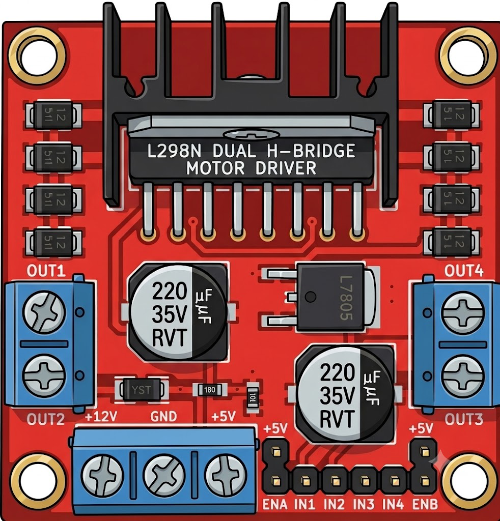
The L298N H-Bridge is a dual full-bridge motor driver designed to control the direction and speed of DC motors and stepper motors. It is widely used in robotics and automation projects due to its ability to drive two motors simultaneously while handling high current and voltage. The module is equipped with onboard heat sinks and protection diodes, ensuring reliable operation in demanding applications.
Explore Projects Built with Puente H L298N
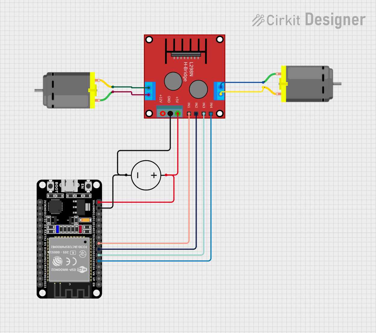
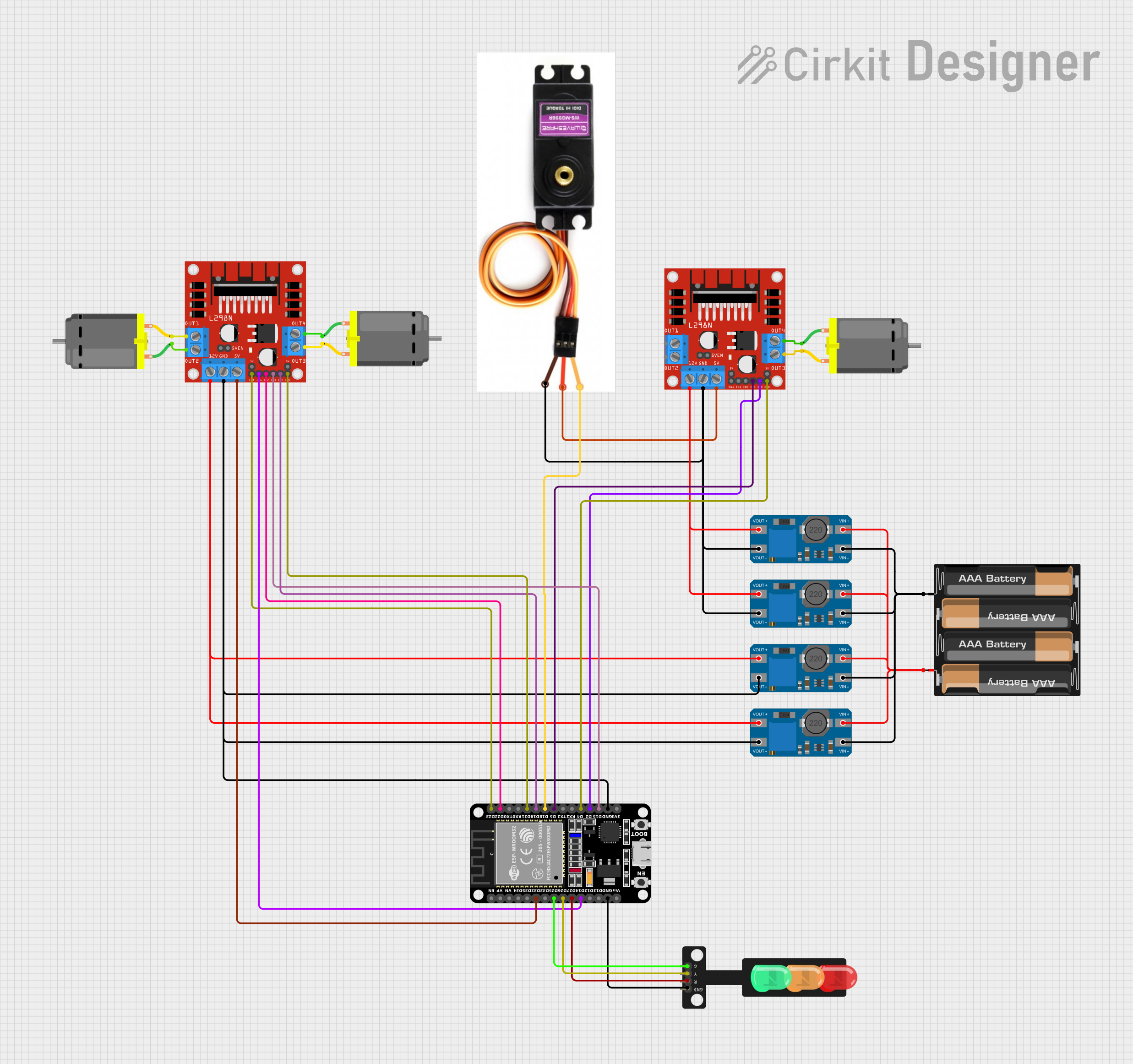
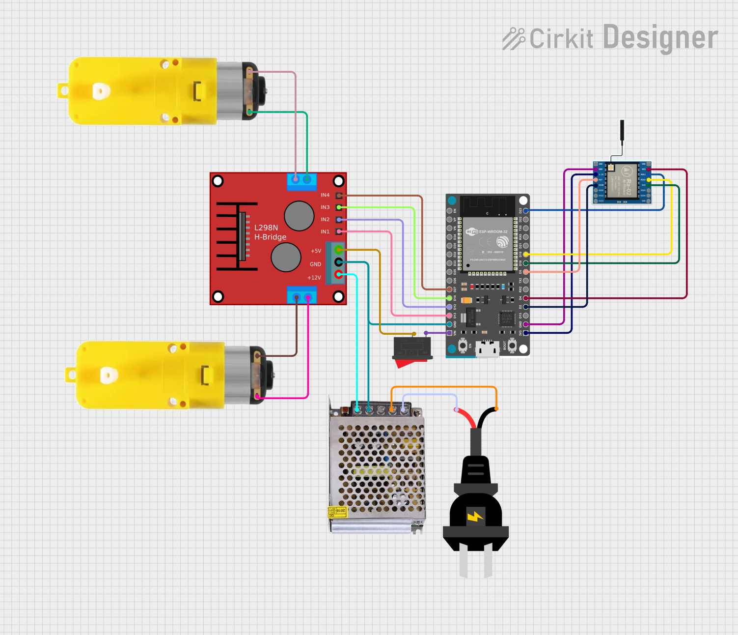
Explore Projects Built with Puente H L298N
Common Applications
- Robotics: Driving wheels or tracks of robots
- Automation: Controlling conveyor belts or actuators
- DIY Projects: Building remote-controlled cars or robotic arms
- Stepper Motor Control: Driving stepper motors for precise positioning
Technical Specifications
Below are the key technical details of the L298N H-Bridge module:
| Parameter | Value |
|---|---|
| Operating Voltage | 5V to 46V |
| Maximum Output Current | 2A per channel (4A total) |
| Logic Voltage | 5V |
| Logic Current | 0 to 36mA |
| Power Dissipation | 25W (with proper heat sinking) |
| Control Signal Voltage | 4.5V to 7V (High) |
| Operating Temperature | -25°C to +130°C |
| Dimensions | 43mm x 43mm x 27mm |
Pin Configuration and Descriptions
The L298N module has multiple pins and terminals for motor control and power input. Below is the pinout:
| Pin/Terminal | Description |
|---|---|
| IN1 | Input pin to control Motor A direction (High/Low) |
| IN2 | Input pin to control Motor A direction (High/Low) |
| IN3 | Input pin to control Motor B direction (High/Low) |
| IN4 | Input pin to control Motor B direction (High/Low) |
| ENA | Enable pin for Motor A (PWM input for speed control) |
| ENB | Enable pin for Motor B (PWM input for speed control) |
| OUT1 | Output pin connected to Motor A terminal 1 |
| OUT2 | Output pin connected to Motor A terminal 2 |
| OUT3 | Output pin connected to Motor B terminal 1 |
| OUT4 | Output pin connected to Motor B terminal 2 |
| 12V | Power supply for motors (up to 46V) |
| 5V | Logic voltage supply (can be used to power the module if jumper is connected) |
| GND | Ground connection |
Usage Instructions
How to Use the L298N in a Circuit
Power Connections:
- Connect the
12Vterminal to the motor power supply (e.g., a battery or DC power source). - Connect the
GNDterminal to the ground of the power supply and the circuit. - If the motor power supply is 12V or less, you can use the onboard 5V regulator by placing the jumper on the
5Vpin. This will power the logic circuit.
- Connect the
Motor Connections:
- Connect the motor terminals to
OUT1andOUT2for Motor A, andOUT3andOUT4for Motor B.
- Connect the motor terminals to
Control Connections:
- Connect the
IN1,IN2,IN3, andIN4pins to the microcontroller's digital output pins. - Use
ENAandENBpins for speed control by providing a PWM signal.
- Connect the
Logic Power:
- If the jumper is removed from the
5Vpin, provide an external 5V logic supply to the5Vpin.
- If the jumper is removed from the
Important Considerations
- Ensure the motor's current and voltage ratings are within the L298N's specifications.
- Use heat sinks or cooling fans if the module operates near its maximum current capacity.
- Avoid reversing the polarity of the power supply to prevent damage to the module.
Example: Controlling a DC Motor with Arduino UNO
Below is an example code to control the direction and speed of a DC motor connected to Motor A:
// Define L298N pins connected to Arduino
#define IN1 7  // IN1 pin for Motor A direction control
#define IN2 8  // IN2 pin for Motor A direction control
#define ENA 9  // ENA pin for Motor A speed control (PWM)

// Setup function
void setup() {
  pinMode(IN1, OUTPUT); // Set IN1 as output
  pinMode(IN2, OUTPUT); // Set IN2 as output
  pinMode(ENA, OUTPUT); // Set ENA as output
}

// Loop function
void loop() {
  // Rotate motor in one direction
  digitalWrite(IN1, HIGH); // Set IN1 HIGH
  digitalWrite(IN2, LOW);  // Set IN2 LOW
  analogWrite(ENA, 150);   // Set speed to 150 (range: 0-255)
  delay(2000);             // Run for 2 seconds

  // Stop the motor
  analogWrite(ENA, 0);     // Set speed to 0
  delay(1000);             // Wait for 1 second

  // Rotate motor in the opposite direction
  digitalWrite(IN1, LOW);  // Set IN1 LOW
  digitalWrite(IN2, HIGH); // Set IN2 HIGH
  analogWrite(ENA, 200);   // Set speed to 200 (range: 0-255)
  delay(2000);             // Run for 2 seconds

  // Stop the motor
  analogWrite(ENA, 0);     // Set speed to 0
  delay(1000);             // Wait for 1 second
}
Troubleshooting and FAQs
Common Issues
Motor Not Spinning:
- Check the power supply connections to ensure proper voltage and polarity.
- Verify that the
ENAorENBpins are receiving a PWM signal or are set to HIGH.
Overheating:
- Ensure the motor's current does not exceed 2A per channel.
- Use a heat sink or cooling fan if the module becomes too hot.
No Response from Motors:
- Confirm that the control pins (
IN1,IN2, etc.) are correctly connected to the microcontroller. - Check for loose connections or damaged wires.
- Confirm that the control pins (
FAQs
Q: Can I control stepper motors with the L298N?
A: Yes, the L298N can control stepper motors by driving the coils in sequence. You will need to use both channels (Motor A and Motor B) for one stepper motor.
Q: What happens if I exceed the current rating?
A: Exceeding the current rating can damage the module. Use motors within the specified current limits or add external current-limiting resistors.
Q: Can I use the onboard 5V regulator to power my Arduino?
A: Yes, if the motor power supply is 12V or less, the onboard 5V regulator can provide power to the Arduino via the 5V pin. However, ensure the total current draw does not exceed the regulator's capacity.