
How to Use GY-BNO08X IMU: Examples, Pinouts, and Specs
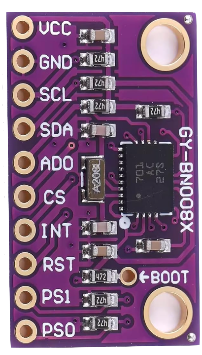
 Design with GY-BNO08X IMU in Cirkit Designer
Introduction
The GY-BNO08X is an advanced Inertial Measurement Unit (IMU) that integrates a 3-axis accelerometer, 3-axis gyroscope, and 3-axis magnetometer. It features a built-in sensor fusion algorithm, enabling it to provide highly accurate orientation, heading, and motion data. This makes it an ideal choice for applications requiring precise motion tracking and spatial awareness.
Explore Projects Built with GY-BNO08X IMU
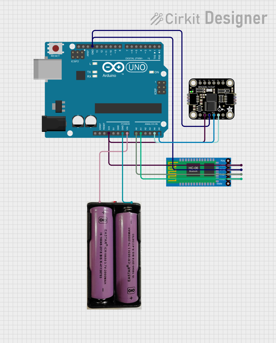 Open Project in Cirkit Designer
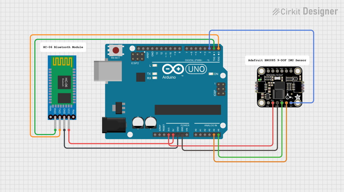 Open Project in Cirkit Designer
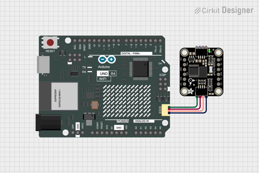 Open Project in Cirkit Designer
 Open Project in Cirkit Designer
Explore Projects Built with GY-BNO08X IMU
Open Project in Cirkit DesignerOpen Project in Cirkit DesignerOpen Project in Cirkit DesignerOpen Project in Cirkit DesignerCommon Applications
- Robotics for navigation and control
- Drones for stabilization and orientation
- Virtual reality (VR) and augmented reality (AR) systems
- Wearable devices for motion tracking
- Gaming controllers and motion-based input devices
Technical Specifications
The GY-BNO08X is a versatile IMU with the following key specifications:
| Parameter | Value |
|---|---|
| Operating Voltage | 3.3V - 5V |
| Communication Protocols | I2C, SPI, UART |
| Accelerometer Range | ±2g, ±4g, ±8g, ±16g |
| Gyroscope Range | ±125°/s, ±250°/s, ±500°/s, ±1000°/s, ±2000°/s |
| Magnetometer Range | ±4900 µT |
| Orientation Output | Quaternion, Euler angles |
| Operating Temperature | -40°C to +85°C |
| Dimensions | 15mm x 15mm |
Pin Configuration
The GY-BNO08X module has the following pinout:
| Pin | Name | Description |
|---|---|---|
| 1 | VIN | Power input (3.3V - 5V) |
| 2 | GND | Ground |
| 3 | SDA | I2C data line |
| 4 | SCL | I2C clock line |
| 5 | INT | Interrupt pin (optional, for data-ready signal) |
| 6 | PS0 | Protocol selection (connect to GND for I2C) |
| 7 | PS1 | Protocol selection (connect to GND for I2C) |
| 8 | RST | Reset pin (active low) |
Usage Instructions
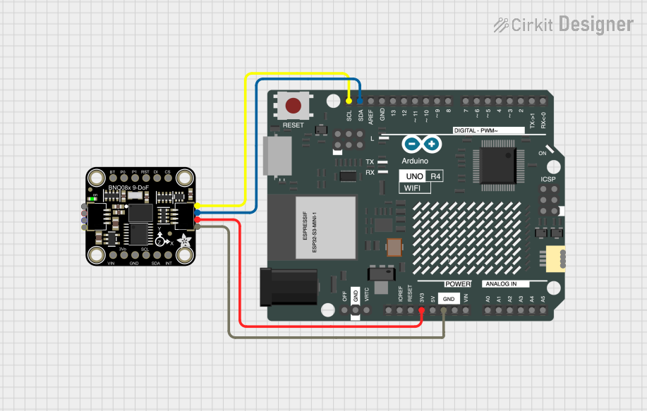
Connecting the GY-BNO08X to an Arduino UNO
To use the GY-BNO08X with an Arduino UNO, follow these steps:
- Connect the VIN pin of the GY-BNO08X to the 5V pin on the Arduino.
- Connect the GND pin of the GY-BNO08X to the GND pin on the Arduino.
- Connect the SDA pin of the GY-BNO08X to the A4 pin on the Arduino (I2C data line).
- Connect the SCL pin of the GY-BNO08X to the A5 pin on the Arduino (I2C clock line).
- Ensure the PS0 and PS1 pins are connected to GND to enable I2C communication.
Sample Arduino Code
Below is an example Arduino sketch to read orientation data from the GY-BNO08X using I2C:
#include <Wire.h>
#include <Adafruit_BNO08x.h>

// Create an instance of the BNO08X sensor
Adafruit_BNO08x bno08x;

// Define the I2C address of the GY-BNO08X
#define BNO08X_I2C_ADDRESS 0x4A

void setup() {
  Serial.begin(115200); // Initialize serial communication for debugging
  Wire.begin();         // Initialize I2C communication

  // Initialize the BNO08X sensor
  if (!bno08x.begin_I2C(BNO08X_I2C_ADDRESS)) {
    Serial.println("Failed to initialize BNO08X! Check connections.");
    while (1); // Halt execution if initialization fails
  }

  Serial.println("BNO08X initialized successfully!");

  // Enable orientation reporting
  if (!bno08x.enableReport(SH2_ARVR_STABILIZED_RV)) {
    Serial.println("Failed to enable orientation reporting!");
    while (1); // Halt execution if enabling fails
  }
}

void loop() {
  // Check if new orientation data is available
  if (bno08x.getEvent()) {
    // Retrieve quaternion data
    sh2_SensorValue_t sensorValue = bno08x.getSensorValue();
    float qw = sensorValue.un.arvrStabilizedRV.real;
    float qx = sensorValue.un.arvrStabilizedRV.i;
    float qy = sensorValue.un.arvrStabilizedRV.j;
    float qz = sensorValue.un.arvrStabilizedRV.k;

    // Print quaternion data to the serial monitor
    Serial.print("Quaternion: ");
    Serial.print("qw = "); Serial.print(qw, 4);
    Serial.print(", qx = "); Serial.print(qx, 4);
    Serial.print(", qy = "); Serial.print(qy, 4);
    Serial.print(", qz = "); Serial.println(qz, 4);
  }

  delay(100); // Delay to reduce output frequency
}
Important Considerations
- Ensure the I2C pull-up resistors are present on the SDA and SCL lines. Most breakout boards include these resistors by default.
- The GY-BNO08X operates at 3.3V logic levels. If using a 5V microcontroller, ensure the module is 5V-tolerant or use a level shifter.
- Avoid placing the module near strong magnetic fields or vibrations, as these can affect sensor accuracy.
Troubleshooting and FAQs
Common Issues
The sensor is not detected on the I2C bus.
- Ensure the PS0 and PS1 pins are connected to GND for I2C mode.
- Verify the wiring and check for loose connections.
- Use an I2C scanner sketch to confirm the sensor's address.
Orientation data is inaccurate or unstable.
- Ensure the module is mounted securely and away from sources of vibration.
- Perform a calibration procedure if the sensor supports it.
The Arduino sketch fails to initialize the sensor.
- Double-check the I2C address in the code. The default address is
0x4A. - Ensure the correct library (
Adafruit_BNO08x) is installed and included.
- Double-check the I2C address in the code. The default address is
Tips for Troubleshooting
- Use a logic analyzer or oscilloscope to verify I2C communication if issues persist.
- Test the module with a different microcontroller or development board to rule out hardware issues.
- Refer to the GY-BNO08X datasheet for advanced configuration options and troubleshooting steps.