How to Use magnetic contactor: Examples, Pinouts, and Specs
Introduction
A magnetic contactor is an electromechanical switch used for switching an electrical power circuit. It is essentially a heavy-duty relay with high current ratings, commonly used in industrial and commercial electric power systems. Magnetic contactors are designed to control the flow of electricity to large loads, such as motors, heating elements, and lighting systems, with the advantage of being operated remotely and capable of handling high-power applications.
Explore Projects Built with magnetic contactor


Explore Projects Built with magnetic contactor
Common Applications and Use Cases
- Motor control for industrial machinery
- Electric heater control
- Lighting control systems
- HVAC systems
- Power supply switching
Technical Specifications
Key Technical Details
| Specification | Detail |
|---|---|
| Rated Voltage | AC 24V to 600V, DC 12V to 600V |
| Rated Current | 5A to 800A (depending on model) |
| Power Ratings | Up to several hundred kilowatts |
| Contact Arrangement | Normally open (NO) or normally closed (NC) |
| Operating Frequency | 50/60 Hz |
| Insulation Voltage | Up to 1000V |
| Utilization Category | AC-3, AC-4 (for motors) |
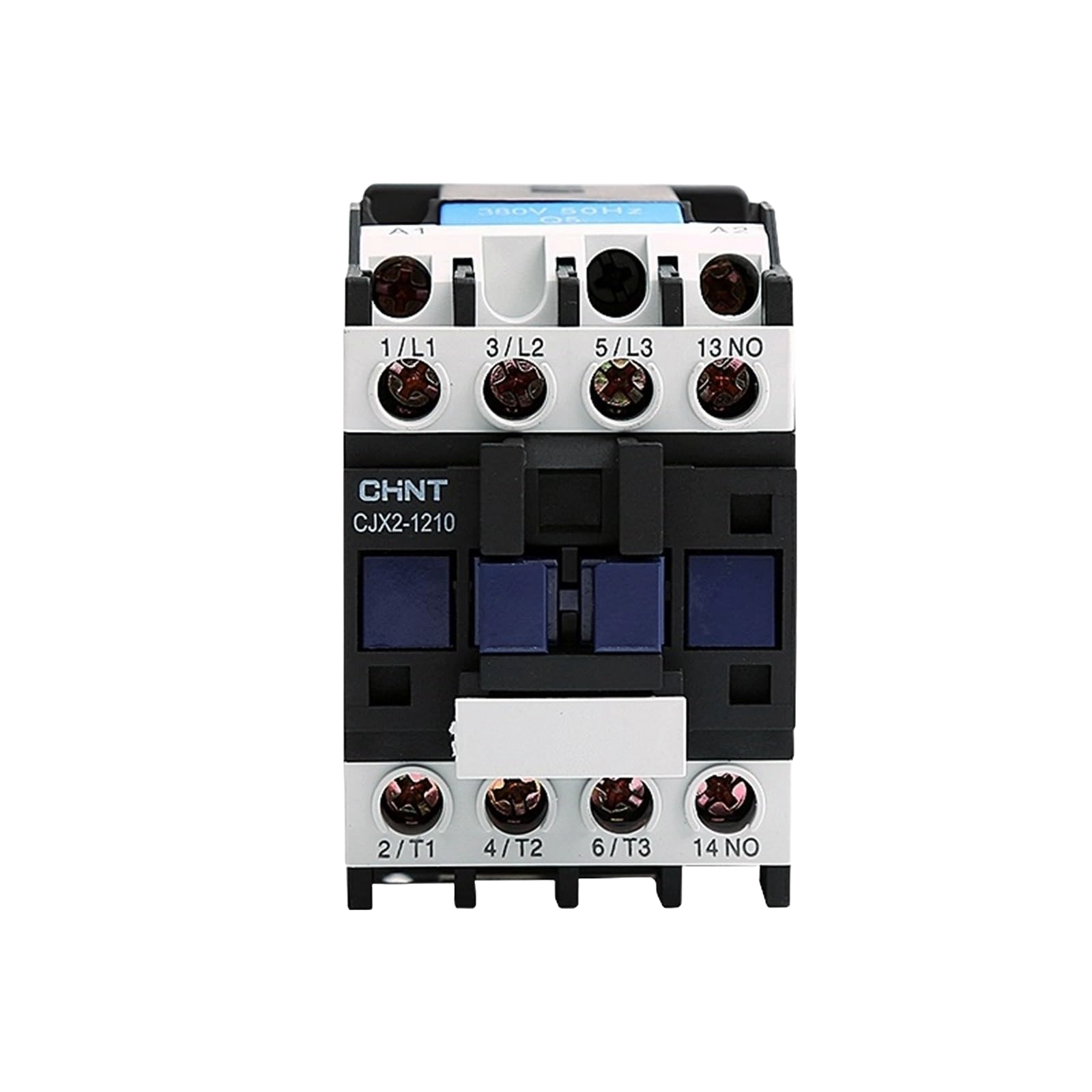
Pin Configuration and Descriptions
| Pin/Contact | Description |
|---|---|
| A1, A2 | Coil terminals; used to energize the contactor |
| NO | Normally open contacts; close when the coil is energized |
| NC | Normally closed contacts; open when the coil is energized |
| T1, T2, T3 | Power output terminals; connected to the load |
| L1, L2, L3 | Power input terminals; connected to the power supply |
Usage Instructions
How to Use the Contactor in a Circuit
- Power Supply Connection: Connect the power supply to the input terminals L1, L2, and L3.
- Load Connection: Connect the load to the output terminals T1, T2, and T3.
- Control Circuit Connection: Connect the control circuit to the coil terminals A1 and A2. Ensure that the control voltage matches the coil's rated voltage.
- Operation: Apply the control voltage to the coil to switch the contactor. The NO contacts will close, and the NC contacts will open, allowing power to flow to the load.
Important Considerations and Best Practices
- Always verify the contactor's voltage and current ratings match the application.
- Use appropriate overcurrent protection devices, such as fuses or circuit breakers.
- Ensure proper ventilation around the contactor to prevent overheating.
- Use auxiliary contacts for feedback signals if required for control purposes.
- Regularly inspect and maintain the contactor to ensure reliable operation.
Troubleshooting and FAQs
Common Issues
- Contactor Does Not Operate: Check the control circuit for proper voltage and connections. Inspect the coil for continuity.
- Contacts Not Closing: Verify that the coil is receiving the correct voltage. Inspect the contacts for damage or obstructions.
- Overheating: Ensure the contactor is not overloaded. Check for adequate ventilation and proper sizing of the contactor for the load.
Solutions and Tips
- If the contactor coil is not energizing, check for a blown control circuit fuse or a faulty control switch.
- For contacts that do not close, ensure that the contactor is not mechanically jammed and that the contacts are clean and free of debris.
- In case of overheating, confirm that the contactor is rated for the load's current and that there are no loose connections causing high resistance.
FAQs
Q: Can a magnetic contactor be used for both AC and DC applications? A: Yes, but ensure the contactor is rated for the specific voltage and current of the application.
Q: How often should a magnetic contactor be maintained? A: It depends on the operating environment and frequency of use. Regular inspections are recommended, with maintenance performed as needed.
Q: What is the difference between a contactor and a relay? A: Contactors are designed for high-power applications, while relays are typically used for lower power signals. Contactors also usually have higher current and voltage ratings than relays.
Q: Can I manually operate the contactor? A: Some contactors come with a manual operation feature, but it is primarily designed for remote electrical operation.
Q: What does the utilization category AC-3 and AC-4 mean? A: These are classifications that indicate the type of load the contactor is designed to control. AC-3 is for squirrel-cage motors: starting, switching off running motors. AC-4 is for duty with starting, plugging, inching, and stalling conditions with high starting current and frequent start/stops.
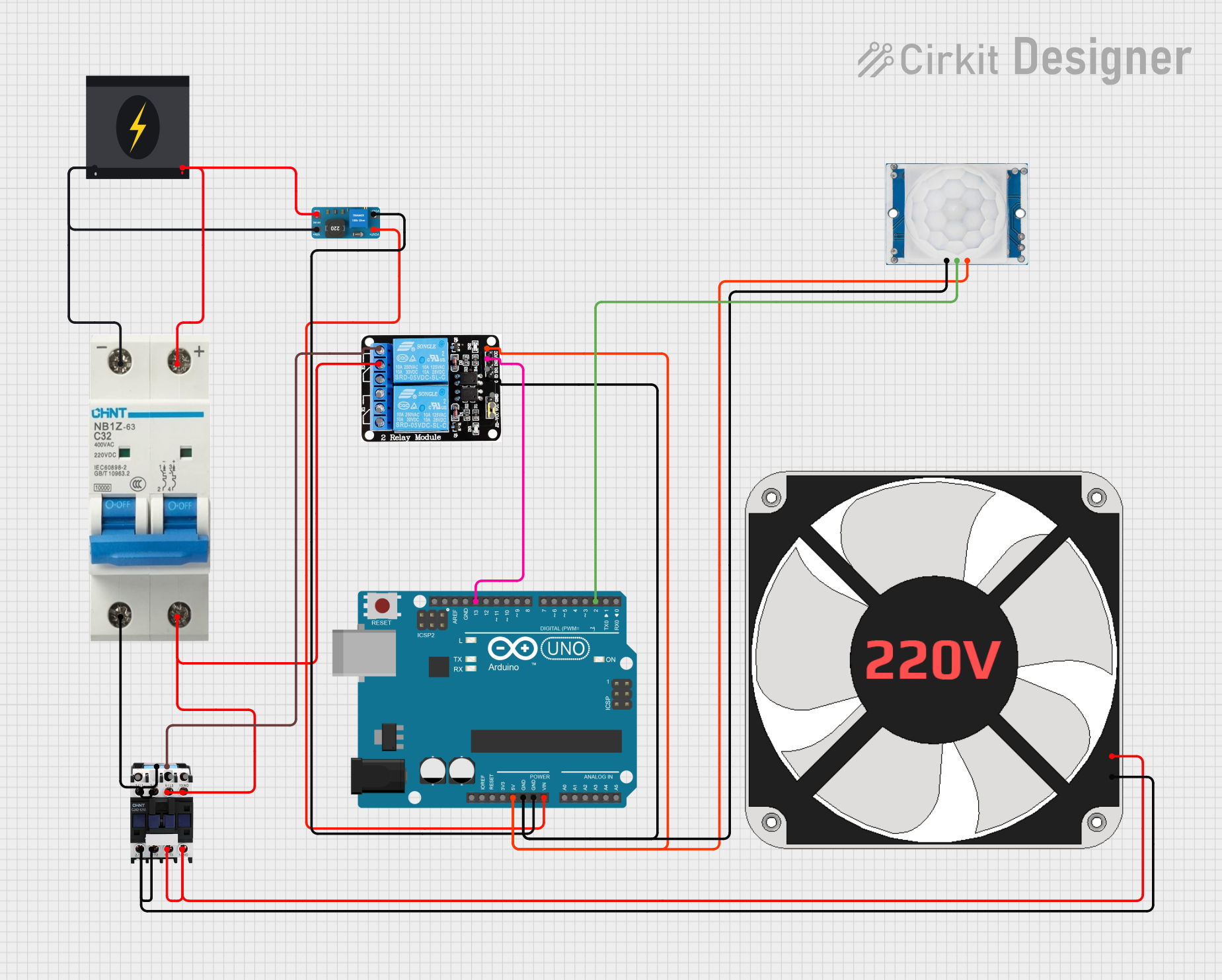
Example Code for Arduino UNO Control
// Define the control pin for the contactor
const int contactorPin = 7;

void setup() {
  // Set the contactor control pin as an output
  pinMode(contactorPin, OUTPUT);
}

void loop() {
  // Energize the contactor coil to close the contacts
  digitalWrite(contactorPin, HIGH);
  delay(5000); // Keep the contactor closed for 5 seconds

  // De-energize the coil to open the contacts
  digitalWrite(contactorPin, LOW);
  delay(5000); // Keep the contactor open for 5 seconds
}
Note: The above code assumes the use of a relay module or a transistor to interface the Arduino with the contactor coil, as the Arduino cannot directly drive the high current required by the contactor coil. Always ensure that the interfacing circuitry is correctly rated for the contactor's coil voltage and current.