
Cirkit Designer
Your all-in-one circuit design IDE
Home /
Component Documentation
How to Use motor and wheels: Examples, Pinouts, and Specs
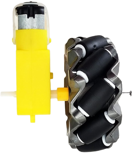
 Design with motor and wheels in Cirkit Designer
Introduction
- The motor and wheels component is a fundamental part of robotics and automation systems. It consists of a motor (typically a DC motor or stepper motor) coupled with wheels to enable movement and mobility in robotic platforms or vehicles.
- Common applications include robotic cars, automated guided vehicles (AGVs), line-following robots, and other mobile robotic systems.
Explore Projects Built with motor and wheels
Battery-Powered Dual Gearmotor Drive System

This circuit consists of a 6V battery pack connected in parallel to two DC gearmotors, one for the left wheel and one for the right wheel of a vehicle. The battery provides power directly to both motors, enabling them to run simultaneously. As there is no control circuitry or microcontroller code provided, the motors will run continuously when the circuit is powered.
Open Project in Cirkit DesignerArduino-Controlled Robotic Vehicle with IR Sensors and L298N Motor Driver
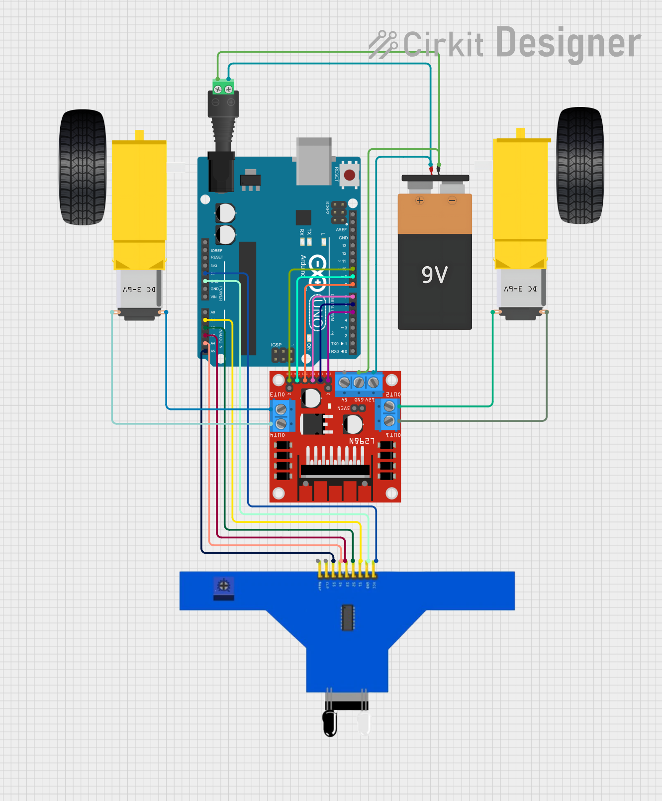
This circuit is designed to control a pair of DC gearmotors using an L298N motor driver module, which is interfaced with an Arduino UNO microcontroller. The Arduino is also connected to a 5-channel IR sensor for input, which may be used for line tracking or obstacle detection. Power is supplied by a 9V battery connected through a 2.1mm barrel jack, and the motor driver module regulates this power to drive the left and right gearmotors for a mobile robot platform.
Open Project in Cirkit DesignerESP32-CAM Controlled Wi-Fi Robot Car
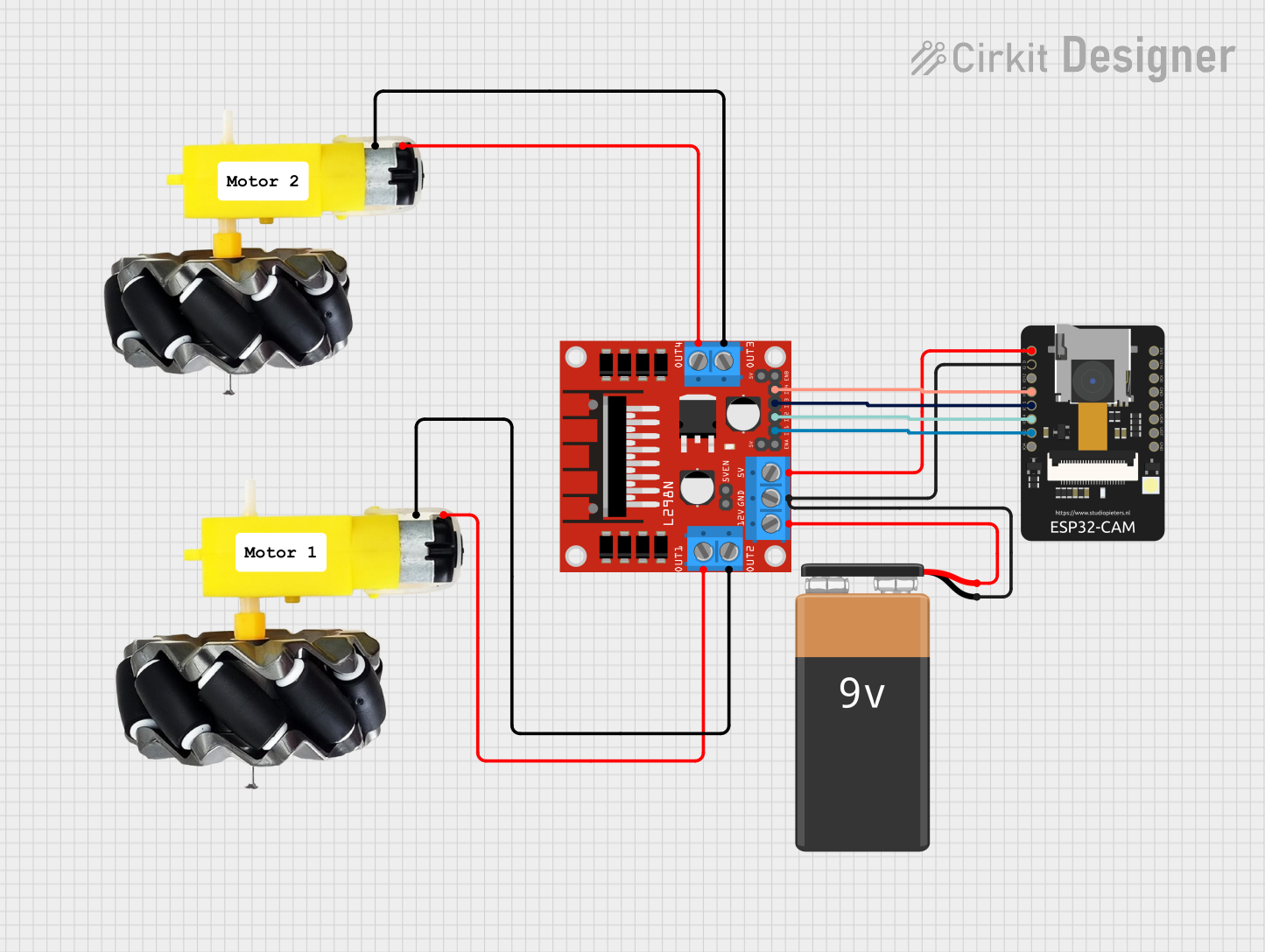
This circuit is designed to control a two-wheel motorized vehicle using an ESP32-CAM microcontroller. The ESP32-CAM is interfaced with an L298N DC motor driver to control the direction and speed of the motors attached to the wheels. Additionally, the ESP32-CAM is configured to capture images and provide WiFi connectivity for remote control via a web server with a user interface for driving commands.
Open Project in Cirkit DesignerESP32 and L298N Motor Driver-Based Wi-Fi Controlled Robotic Vehicle with GPS and Metal Detection
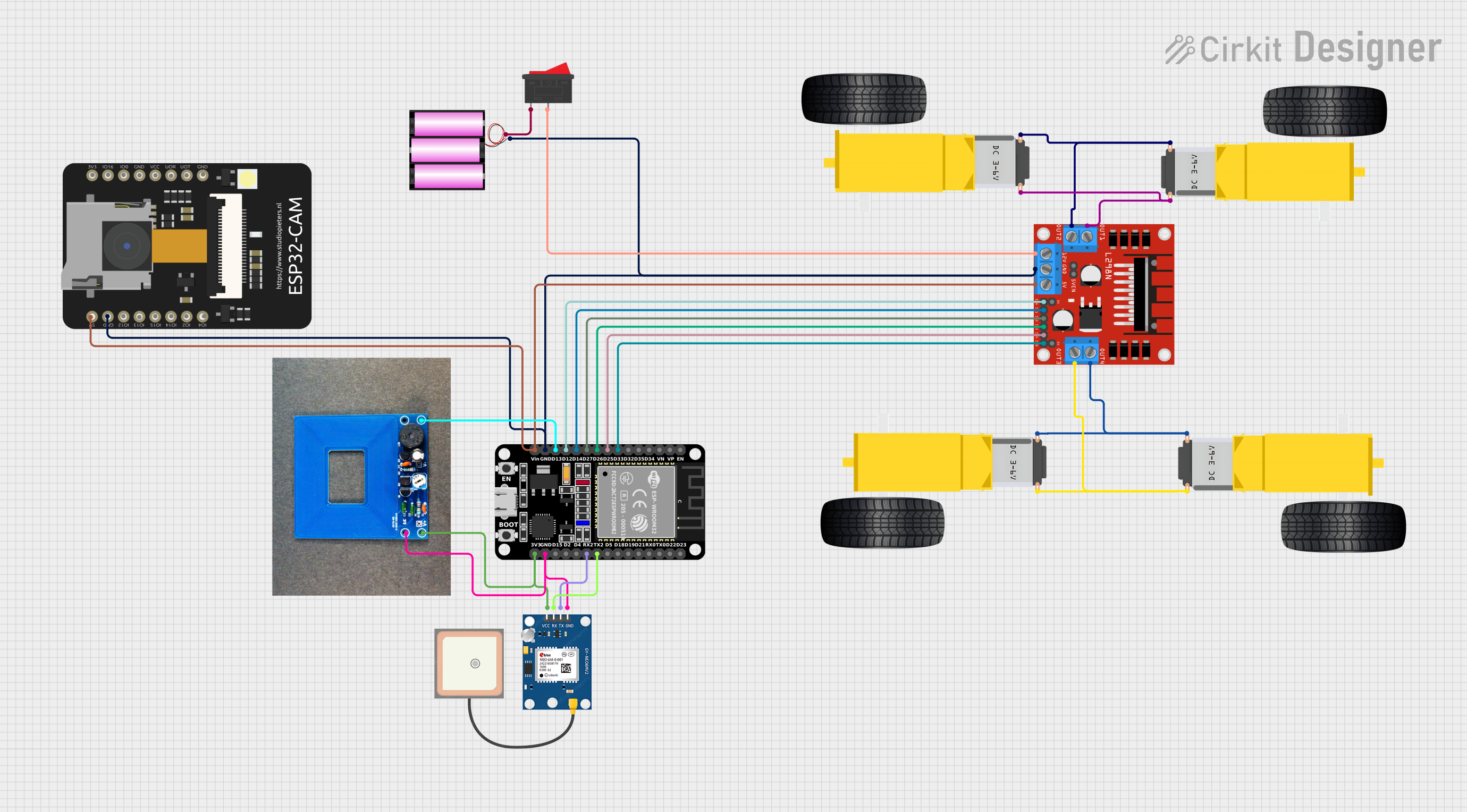
This circuit is a robotic vehicle control system that uses an ESP32 microcontroller to drive four DC gear motors via an L298N motor driver. It also includes a GPS module for location tracking, a metal detector for object detection, and an ESP32 CAM for capturing images or video, all powered by a 12V battery.
Open Project in Cirkit DesignerExplore Projects Built with motor and wheels
Battery-Powered Dual Gearmotor Drive System
This circuit consists of a 6V battery pack connected in parallel to two DC gearmotors, one for the left wheel and one for the right wheel of a vehicle. The battery provides power directly to both motors, enabling them to run simultaneously. As there is no control circuitry or microcontroller code provided, the motors will run continuously when the circuit is powered.
Open Project in Cirkit DesignerArduino-Controlled Robotic Vehicle with IR Sensors and L298N Motor Driver
This circuit is designed to control a pair of DC gearmotors using an L298N motor driver module, which is interfaced with an Arduino UNO microcontroller. The Arduino is also connected to a 5-channel IR sensor for input, which may be used for line tracking or obstacle detection. Power is supplied by a 9V battery connected through a 2.1mm barrel jack, and the motor driver module regulates this power to drive the left and right gearmotors for a mobile robot platform.
Open Project in Cirkit DesignerESP32-CAM Controlled Wi-Fi Robot Car
This circuit is designed to control a two-wheel motorized vehicle using an ESP32-CAM microcontroller. The ESP32-CAM is interfaced with an L298N DC motor driver to control the direction and speed of the motors attached to the wheels. Additionally, the ESP32-CAM is configured to capture images and provide WiFi connectivity for remote control via a web server with a user interface for driving commands.
Open Project in Cirkit DesignerESP32 and L298N Motor Driver-Based Wi-Fi Controlled Robotic Vehicle with GPS and Metal Detection
This circuit is a robotic vehicle control system that uses an ESP32 microcontroller to drive four DC gear motors via an L298N motor driver. It also includes a GPS module for location tracking, a metal detector for object detection, and an ESP32 CAM for capturing images or video, all powered by a 12V battery.
Open Project in Cirkit DesignerTechnical Specifications
- Motor Type: DC motor or stepper motor (varies by model)
- Operating Voltage: 3V to 12V (typical range for DC motors)
- Current Consumption: 100mA to 2A (depending on load and motor type)
- Wheel Diameter: 65mm (common size, may vary)
- Wheel Material: Rubber or plastic with rubberized tread for better traction
- Torque: 0.5 kg-cm to 5 kg-cm (varies by motor)
- Speed: 50 RPM to 300 RPM (varies by motor and voltage)
Pin Configuration and Descriptions
For a DC motor with wheels, the pin configuration typically involves two terminals for motor connections. If used with a motor driver, the pin configuration will depend on the driver.
Motor Driver Pin Configuration (e.g., L298N Motor Driver)
| Pin Name | Description |
|---|---|
| IN1 | Input pin 1 for controlling motor direction (connect to microcontroller) |
| IN2 | Input pin 2 for controlling motor direction (connect to microcontroller) |
| ENA | Enable pin for motor A (connect to PWM pin for speed control) |
| OUT1 | Output pin 1 connected to one terminal of the motor |
| OUT2 | Output pin 2 connected to the other terminal of the motor |
| VCC | Power supply for the motor (e.g., 5V or 12V, depending on motor specs) |
| GND | Ground connection |
Usage Instructions
Connecting the Motor and Wheels:
- Attach the wheels securely to the motor shaft using screws or press-fit mechanisms.
- Connect the motor terminals to a motor driver (e.g., L298N) to control speed and direction.
- Ensure the motor driver is powered with the appropriate voltage and current.
Wiring with an Arduino UNO:
- Connect the motor driver pins (e.g., IN1, IN2, ENA) to the Arduino's digital pins.
- Use a PWM pin on the Arduino to control the motor speed via the ENA pin.
- Provide a separate power supply for the motor driver if the motor requires higher current.
Arduino Code Example:
// Motor and wheels control using L298N motor driver and Arduino UNO
const int IN1 = 9;  // Motor direction control pin 1
const int IN2 = 8;  // Motor direction control pin 2
const int ENA = 10; // Motor speed control (PWM pin)

void setup() {
  pinMode(IN1, OUTPUT); // Set IN1 as output
  pinMode(IN2, OUTPUT); // Set IN2 as output
  pinMode(ENA, OUTPUT); // Set ENA as output
}

void loop() {
  // Move forward
  digitalWrite(IN1, HIGH); // Set IN1 high
  digitalWrite(IN2, LOW);  // Set IN2 low
  analogWrite(ENA, 150);   // Set speed (0-255)

  delay(2000); // Move forward for 2 seconds

  // Move backward
  digitalWrite(IN1, LOW);  // Set IN1 low
  digitalWrite(IN2, HIGH); // Set IN2 high
  analogWrite(ENA, 150);   // Set speed (0-255)

  delay(2000); // Move backward for 2 seconds

  // Stop
  digitalWrite(IN1, LOW);  // Set IN1 low
  digitalWrite(IN2, LOW);  // Set IN2 low
  analogWrite(ENA, 0);     // Set speed to 0

  delay(2000); // Stop for 2 seconds
}
Important Considerations:
- Ensure the motor driver can handle the current and voltage requirements of the motor.
- Use a separate power supply for the motor if it requires higher current than the Arduino can provide.
- Avoid stalling the motor for extended periods, as it may overheat and get damaged.
Troubleshooting and FAQs
Common Issues
Motor not spinning:
- Check the wiring between the motor, motor driver, and Arduino.
- Ensure the motor driver is receiving sufficient power.
- Verify the Arduino code is correctly uploaded and running.
Motor spinning in the wrong direction:
- Swap the connections of IN1 and IN2 in the code or reverse the motor terminals.
Motor speed is inconsistent:
- Check the power supply voltage and current.
- Ensure the PWM signal is stable and not interrupted.
Motor driver overheating:
- Verify the motor driver is rated for the motor's current.
- Add a heat sink or cooling fan to the motor driver if necessary.
FAQs
Can I use a single power supply for both the Arduino and motor driver?
- Yes, but ensure the power supply can handle the combined current requirements of both components.
What type of wheels should I use for different surfaces?
- Use rubberized wheels for smooth surfaces and larger, treaded wheels for rough or uneven terrain.
Can I control multiple motors with one Arduino?
- Yes, you can control multiple motors using a motor driver with multiple channels (e.g., L298N supports two motors).
By following this documentation, you can effectively integrate and operate motor and wheels components in your projects.