
How to Use Buzzer: Examples, Pinouts, and Specs
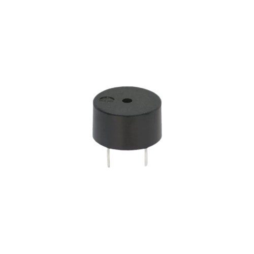
 Design with Buzzer in Cirkit Designer
Introduction
A buzzer is an audio signaling device that produces sound when an electric current passes through it. It is commonly used in alarms, timers, and notification systems to provide audible feedback or alerts. Buzzers are available in two main types: active and passive. Active buzzers generate sound when powered, while passive buzzers require an external signal to produce sound.
Explore Projects Built with Buzzer
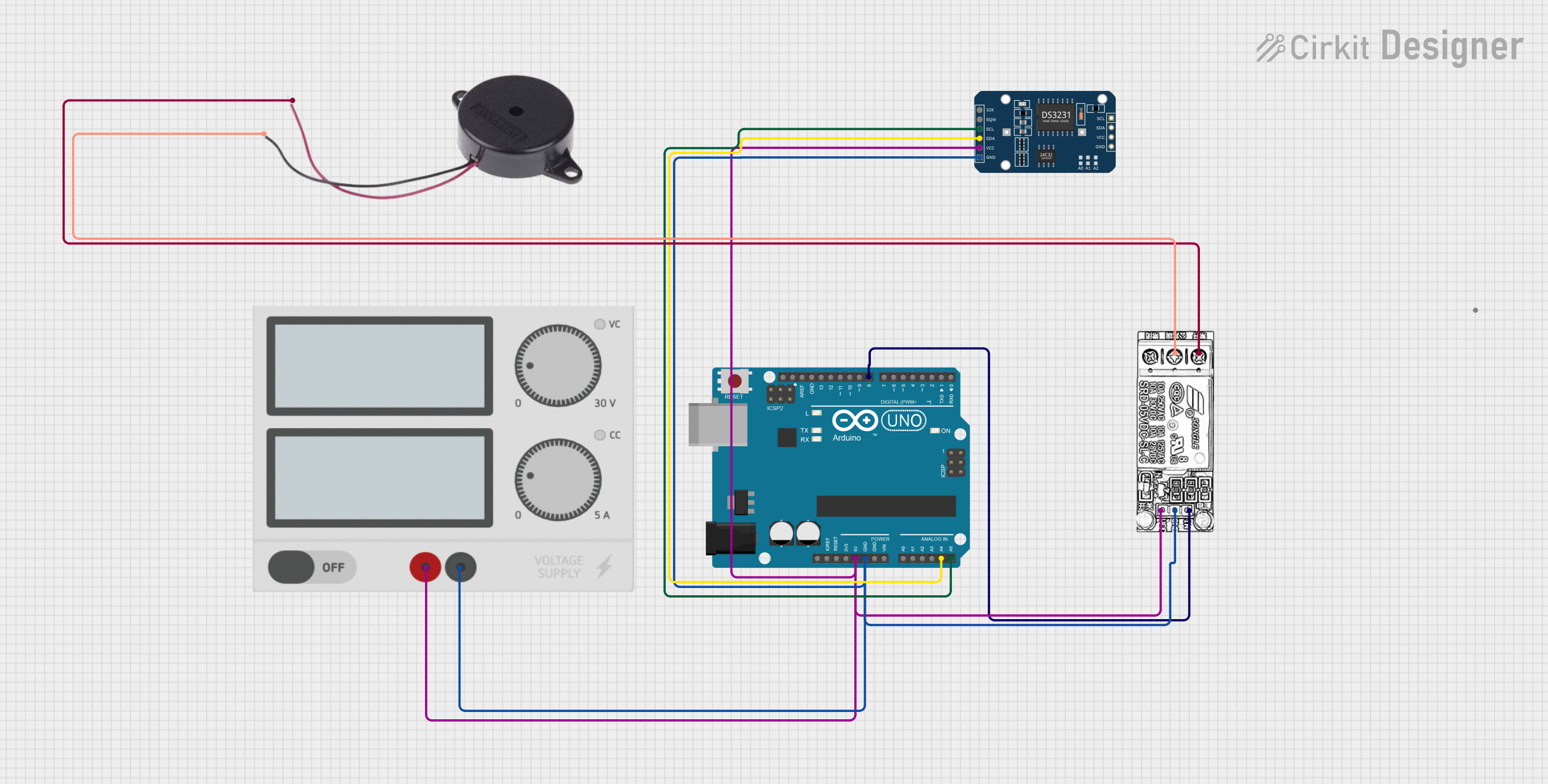 Open Project in Cirkit Designer
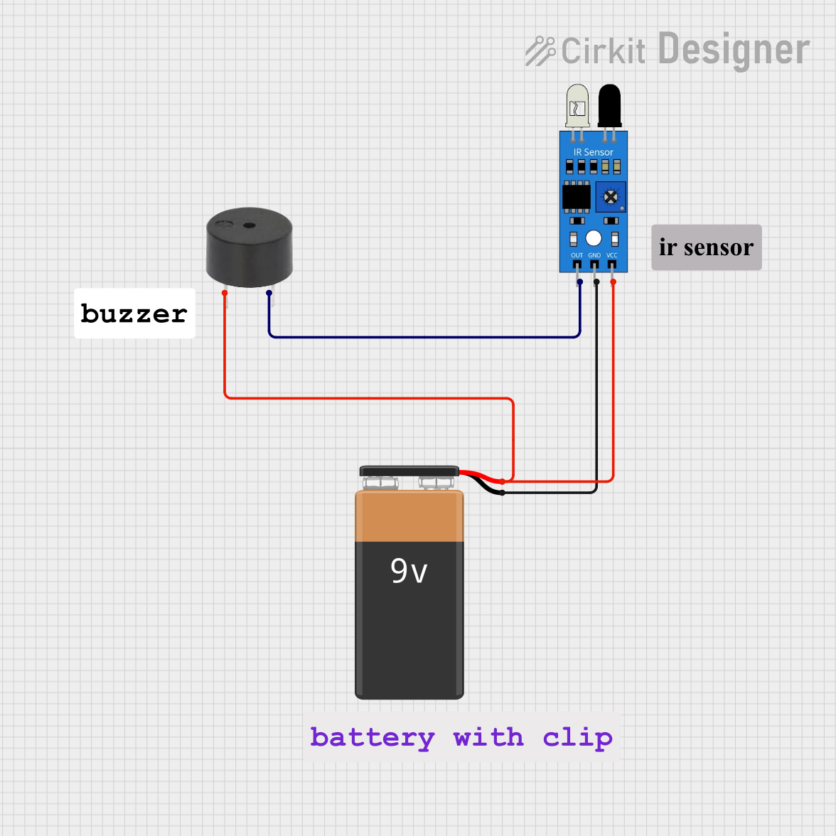 Open Project in Cirkit Designer
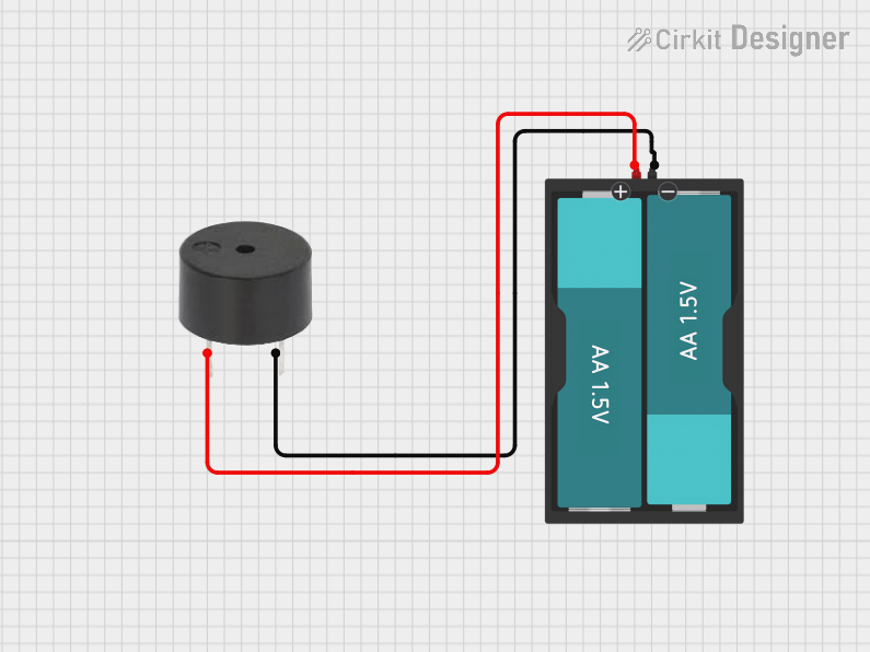 Open Project in Cirkit Designer
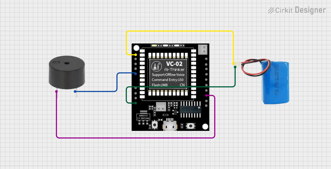 Open Project in Cirkit Designer
Explore Projects Built with Buzzer
Open Project in Cirkit DesignerOpen Project in Cirkit DesignerOpen Project in Cirkit DesignerOpen Project in Cirkit DesignerCommon Applications
- Alarm systems (e.g., fire alarms, security alarms)
- Timers and reminders
- Notification systems in appliances (e.g., microwaves, washing machines)
- Feedback in electronic projects (e.g., Arduino-based systems)
Technical Specifications
Key Technical Details
| Parameter | Value |
|---|---|
| Operating Voltage | 3V to 12V (varies by model) |
| Current Consumption | 5mA to 30mA (depending on type) |
| Sound Frequency | 2 kHz to 4 kHz (typical range) |
| Sound Pressure Level | 85 dB to 100 dB (at 10 cm) |
| Operating Temperature | -20°C to +70°C |
| Dimensions | Varies (e.g., 12mm, 16mm, etc.) |
Pin Configuration and Descriptions
Active Buzzer
| Pin Name | Description |
|---|---|
| Positive (+) | Connect to the positive terminal of the power supply or signal source. |
| Negative (-) | Connect to the ground (GND) of the circuit. |
Passive Buzzer
| Pin Name | Description |
|---|---|
| Signal | Connect to the output of a signal generator (e.g., microcontroller pin). |
| Ground (GND) | Connect to the ground of the circuit. |
Usage Instructions
How to Use the Buzzer in a Circuit
- Identify the Type of Buzzer: Determine whether you are using an active or passive buzzer. Active buzzers only require a power source, while passive buzzers need a signal to generate sound.
- Connect the Pins:
- For an active buzzer, connect the positive pin to the power supply (e.g., 5V) and the negative pin to ground.
- For a passive buzzer, connect the signal pin to a microcontroller or signal generator and the ground pin to the circuit ground.
- Add a Resistor (Optional): To limit current, you may add a resistor in series with the buzzer. A typical value is 220Ω to 1kΩ, depending on the buzzer's specifications.
- Test the Circuit: Power the circuit and verify that the buzzer produces sound.
Important Considerations
- Voltage Compatibility: Ensure the buzzer's operating voltage matches your circuit's power supply.
- Signal Frequency: For passive buzzers, use a signal frequency within the buzzer's specified range (e.g., 2 kHz to 4 kHz) to produce optimal sound.
- Polarity: Active buzzers are polarized, so ensure correct connection of the positive and negative pins.
- Mounting: Secure the buzzer to prevent vibrations or movement that could affect sound quality.
Example: Using a Passive Buzzer with Arduino UNO
// Example code to generate a tone on a passive buzzer using Arduino UNO

// Define the pin connected to the buzzer
const int buzzerPin = 8;

void setup() {
  // Set the buzzer pin as an output
  pinMode(buzzerPin, OUTPUT);
}

void loop() {
  // Generate a 1 kHz tone for 500 milliseconds
  tone(buzzerPin, 1000, 500);
  delay(1000); // Wait for 1 second

  // Generate a 2 kHz tone for 500 milliseconds
  tone(buzzerPin, 2000, 500);
  delay(1000); // Wait for 1 second
}
Notes:
- Use the
tone()function for passive buzzers to generate sound at specific frequencies. - Active buzzers do not require the
tone()function; simply set the pin HIGH or LOW to turn the buzzer on or off.
Troubleshooting and FAQs
Common Issues and Solutions
No Sound from the Buzzer:
- Cause: Incorrect wiring or insufficient voltage.
- Solution: Verify the connections and ensure the power supply matches the buzzer's operating voltage.
Weak or Distorted Sound:
- Cause: Signal frequency is outside the buzzer's range (for passive buzzers).
- Solution: Adjust the signal frequency to match the buzzer's specifications.
Buzzer Overheats:
- Cause: Excessive current due to lack of a current-limiting resistor.
- Solution: Add a resistor in series with the buzzer to limit current.
Buzzer Stays On Constantly:
- Cause: Active buzzer connected directly to power without control.
- Solution: Use a microcontroller or switch to control the buzzer.
FAQs
Q: Can I use a passive buzzer without a microcontroller?
A: Yes, you can use a signal generator or an oscillator circuit to drive a passive buzzer.Q: What is the difference between active and passive buzzers?
A: Active buzzers have an internal oscillator and only need power to produce sound. Passive buzzers require an external signal to generate sound.Q: Can I control the volume of the buzzer?
A: The volume is typically fixed, but you can reduce it by lowering the supply voltage or adding a resistor in series.Q: How do I know if my buzzer is active or passive?
A: Active buzzers will produce sound when connected to a power source, while passive buzzers will not.
By following this documentation, you can effectively integrate a buzzer into your electronic projects and troubleshoot common issues.