How to Use ESP32 Devkit V4: Examples, Pinouts, and Specs
Introduction
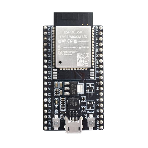
The ESP32 Devkit V4 is a development board featuring the ESP32 microcontroller, which includes Wi-Fi and Bluetooth capabilities. This versatile board is designed for IoT and embedded applications, offering multiple GPIO pins and a range of peripherals. It is widely used in projects that require wireless communication, sensor integration, and real-time data processing.
Explore Projects Built with ESP32 Devkit V4


Explore Projects Built with ESP32 Devkit V4
Common Applications and Use Cases
- IoT Devices: Smart home systems, environmental monitoring, and industrial automation.
- Wearable Technology: Fitness trackers, smartwatches, and health monitoring devices.
- Wireless Communication: Wi-Fi and Bluetooth-based projects, such as remote controls and wireless sensors.
- Embedded Systems: Robotics, automation, and custom hardware solutions.
Technical Specifications
Key Technical Details
| Specification | Value |
|---|---|
| Microcontroller | ESP32 |
| Operating Voltage | 3.3V |
| Input Voltage | 5V (via USB) or 7-12V (via Vin) |
| Digital I/O Pins | 34 |
| Analog Input Pins | 16 (12-bit ADC) |
| Analog Output Pins | 2 (8-bit DAC) |
| Flash Memory | 4MB |
| SRAM | 520KB |
| Wi-Fi | 802.11 b/g/n |
| Bluetooth | v4.2 BR/EDR and BLE |
| Clock Speed | 240 MHz (dual-core) |
| Communication | UART, SPI, I2C, I2S, CAN, PWM |
| Operating Temperature | -40°C to 125°C |
Pin Configuration and Descriptions
| Pin Number | Pin Name | Description |
|---|---|---|
| 1 | EN | Enable (Active High) |
| 2 | IO23 | GPIO23, HSPI MOSI |
| 3 | IO22 | GPIO22, I2C SCL |
| 4 | TXD0 | UART0 Transmit |
| 5 | RXD0 | UART0 Receive |
| 6 | IO21 | GPIO21, I2C SDA |
| 7 | GND | Ground |
| 8 | IO19 | GPIO19, VSPI MISO |
| 9 | IO18 | GPIO18, VSPI SCK |
| 10 | IO5 | GPIO5, VSPI CS0 |
| 11 | IO17 | GPIO17, UART2 TXD |
| 12 | IO16 | GPIO16, UART2 RXD |
| 13 | IO4 | GPIO4, HSPI CS0 |
| 14 | IO0 | GPIO0, Boot Mode Select |
| 15 | IO2 | GPIO2, ADC2_CH2 |
| 16 | IO15 | GPIO15, HSPI SCK |
| 17 | IO13 | GPIO13, HSPI MISO |
| 18 | IO12 | GPIO12, HSPI CS0 |
| 19 | IO14 | GPIO14, HSPI CLK |
| 20 | IO27 | GPIO27, ADC2_CH7 |
| 21 | IO26 | GPIO26, ADC2_CH9 |
| 22 | IO25 | GPIO25, DAC1 |
| 23 | IO33 | GPIO33, ADC1_CH5 |
| 24 | IO32 | GPIO32, ADC1_CH4 |
| 25 | IO35 | GPIO35, ADC1_CH7 |
| 26 | IO34 | GPIO34, ADC1_CH6 |
| 27 | IO39 | GPIO39, ADC1_CH3 |
| 28 | IO36 | GPIO36, ADC1_CH0 |
| 29 | IO3 | GPIO3, UART0 RXD |
| 30 | IO1 | GPIO1, UART0 TXD |
| 31 | IO9 | GPIO9, SD2 |
| 32 | IO10 | GPIO10, SD3 |
| 33 | IO11 | GPIO11, CMD |
| 34 | IO6 | GPIO6, CLK |
| 35 | IO7 | GPIO7, SD0 |
| 36 | IO8 | GPIO8, SD1 |
Usage Instructions
How to Use the Component in a Circuit
Powering the ESP32 Devkit V4:
- Connect the board to your computer using a USB cable. This will provide both power and a communication interface.
- Alternatively, you can power the board using an external power supply (7-12V) connected to the Vin pin.
Programming the ESP32:
- Install the Arduino IDE and add the ESP32 board support by following the instructions on the ESP32 Arduino Core GitHub page.
- Select the appropriate board (ESP32 Dev Module) and port in the Arduino IDE.
- Write your code and upload it to the board.
Connecting Peripherals:
- Use the GPIO pins to connect sensors, actuators, and other peripherals.
- Ensure that the voltage levels are compatible with the ESP32 (3.3V logic).
Important Considerations and Best Practices
- Voltage Levels: The ESP32 operates at 3.3V logic. Ensure that any connected peripherals are also 3.3V compatible or use level shifters.
- Power Supply: When using power-hungry peripherals, consider using an external power supply to avoid overloading the USB port.
- Antenna Placement: For optimal Wi-Fi and Bluetooth performance, ensure that the onboard antenna is not obstructed by metal objects or enclosures.
- Boot Mode: The IO0 pin is used to select the boot mode. Ensure it is not pulled low during normal operation to avoid entering the bootloader mode.
Example Code
Here is a simple example code to connect the ESP32 Devkit V4 to a Wi-Fi network and print the IP address:
#include <WiFi.h>

// Replace with your network credentials
const char* ssid = "your_SSID";
const char* password = "your_PASSWORD";

void setup() {
  Serial.begin(115200);
  delay(10);

  // Connect to Wi-Fi network
  Serial.println();
  Serial.print("Connecting to ");
  Serial.println(ssid);

  WiFi.begin(ssid, password);

  while (WiFi.status() != WL_CONNECTED) {
    delay(500);
    Serial.print(".");
  }

  Serial.println("");
  Serial.println("WiFi connected.");
  Serial.print("IP address: ");
  Serial.println(WiFi.localIP());
}

void loop() {
  // Put your main code here, to run repeatedly
}
Troubleshooting and FAQs
Common Issues Users Might Face
ESP32 Not Connecting to Wi-Fi:
- Solution: Double-check the SSID and password. Ensure that the Wi-Fi network is within range and not using unsupported security protocols.
Serial Monitor Not Displaying Output:
- Solution: Ensure that the correct baud rate (115200) is selected in the Serial Monitor. Verify that the correct port is selected in the Arduino IDE.
Board Not Detected by Computer:
- Solution: Ensure that the USB cable is properly connected and is capable of data transfer. Try a different USB port or cable.
Upload Fails with Timeout Error:
- Solution: Press and hold the BOOT button on the ESP32 Devkit V4 while clicking the upload button in the Arduino IDE. Release the BOOT button once the upload starts.
Solutions and Tips for Troubleshooting
- Check Connections: Ensure that all connections are secure and that there are no loose wires.
- Update Drivers: Make sure that the USB drivers for the ESP32 are up to date.
- Use External Power Supply: If you experience instability, consider using an external power supply to power the ESP32.
- Consult Documentation: Refer to the official ESP32 documentation for more detailed information and troubleshooting tips.
By following this documentation, users should be able to effectively utilize the ESP32 Devkit V4 in their projects, whether they are beginners or experienced developers.