How to Use bc547: Examples, Pinouts, and Specs
Introduction
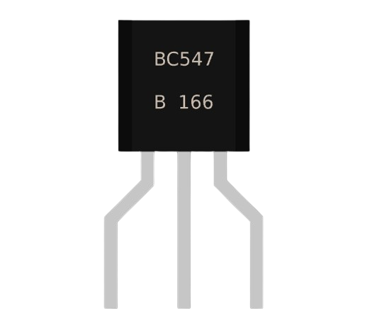
The BC547 is an NPN bipolar junction transistor (BJT) widely used in electronic circuits for amplification and switching purposes. Its versatility and reliability make it a popular choice among hobbyists and professionals alike. The BC547 is known for its low cost, ease of use, and availability, making it an ideal component for various applications.
Explore Projects Built with bc547
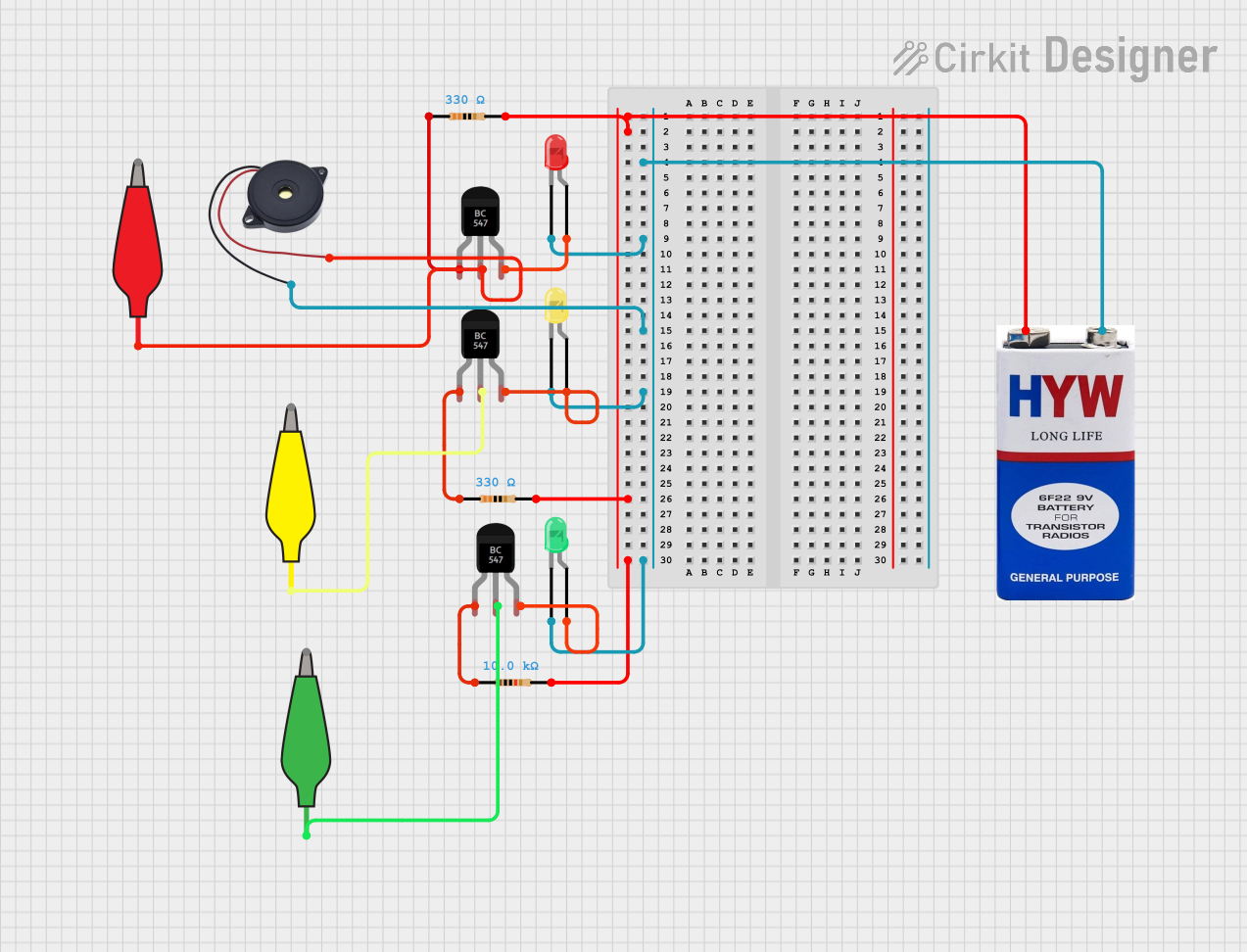
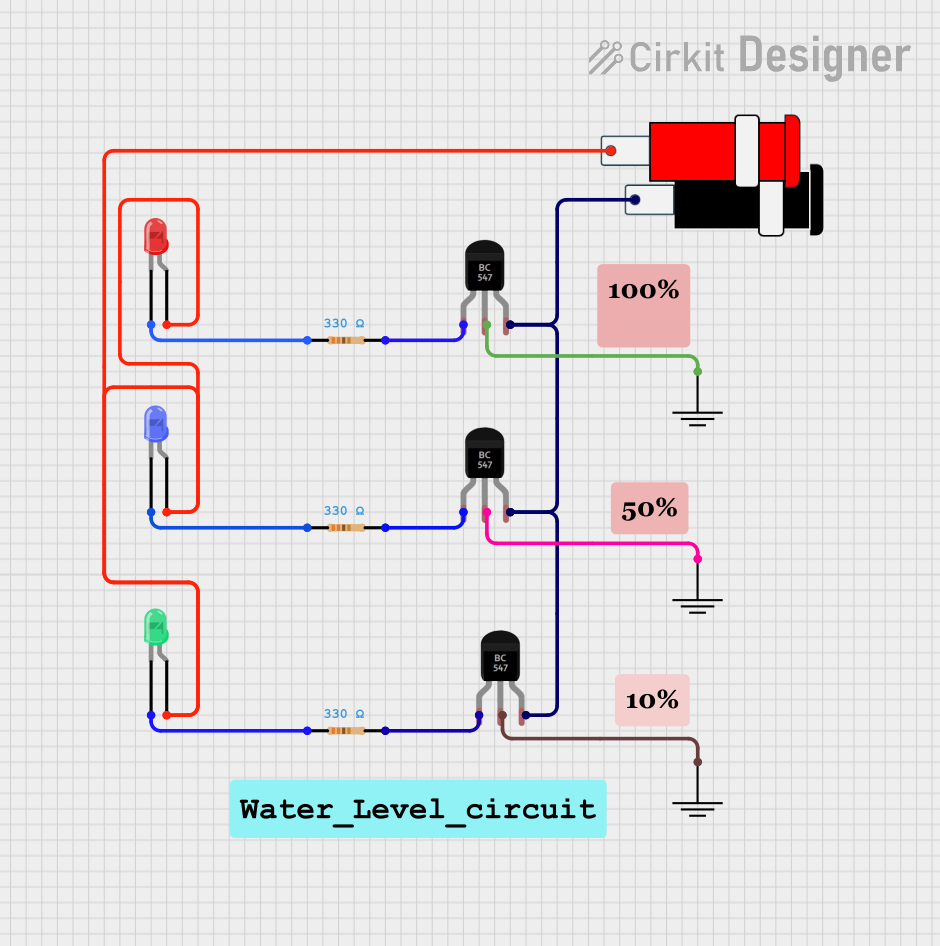
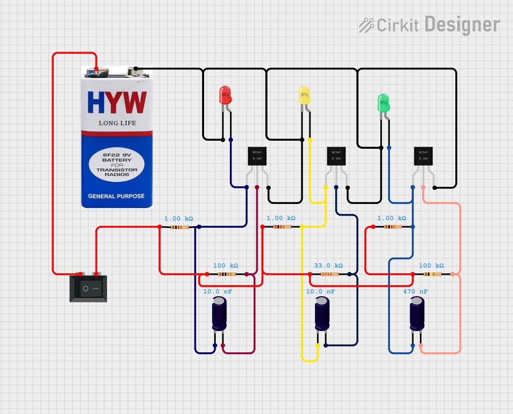
Explore Projects Built with bc547
Common Applications and Use Cases
- Signal Amplification: Used in audio amplifiers, radio frequency amplifiers, and other signal amplification circuits.
- Switching: Employed in switching applications such as relay drivers, LED drivers, and other low-power switching circuits.
- Oscillators: Utilized in oscillator circuits for generating periodic signals.
- Voltage Regulation: Used in voltage regulation circuits to maintain a stable output voltage.
Technical Specifications
Key Technical Details
| Parameter | Value |
|---|---|
| Transistor Type | NPN |
| Maximum Voltage | 45V (Collector-Emitter) |
| Maximum Current | 100mA (Collector Current) |
| Power Dissipation | 500mW |
| DC Current Gain | 110 to 800 (hFE) |
| Transition Frequency | 300 MHz |
| Package Type | TO-92 |
Pin Configuration and Descriptions
| Pin Number | Pin Name | Description |
|---|---|---|
| 1 | Collector | Current flows in through the collector |
| 2 | Base | Controls the transistor's operation |
| 3 | Emitter | Current flows out through the emitter |
Usage Instructions
How to Use the BC547 in a Circuit
- Identify the Pins: Ensure you correctly identify the collector, base, and emitter pins using the pin configuration table above.
- Biasing the Transistor: Apply a small current to the base pin to control the larger current flowing from the collector to the emitter.
- Connecting in a Circuit:
- Amplification: Connect the input signal to the base through a resistor, and the output can be taken from the collector.
- Switching: Use the base to control the switching action, with the load connected to the collector.
Important Considerations and Best Practices
- Current Limiting: Always use a current-limiting resistor in series with the base to prevent excessive current that could damage the transistor.
- Heat Dissipation: Ensure adequate heat dissipation, especially when operating near the maximum power rating.
- Polarity: Double-check the polarity of connections to avoid reverse biasing the transistor, which could lead to malfunction or damage.
Example Circuit with Arduino UNO
Components Required
- BC547 Transistor
- Arduino UNO
- LED
- 220Ω Resistor (for LED)
- 1kΩ Resistor (for base current limiting)
- Breadboard and Jumper Wires
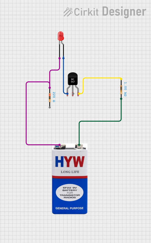
Circuit Diagram
Arduino UNO
+5V  ----->| 220Ω Resistor |----->| LED |----->| Collector (BC547)
GND  ----------------------------->| Emitter (BC547)
Pin 9 ----->| 1kΩ Resistor |----->| Base (BC547)
Arduino Code
// Define the pin connected to the base of the BC547 transistor
const int transistorBasePin = 9;

void setup() {
  // Set the transistor base pin as an output
  pinMode(transistorBasePin, OUTPUT);
}

void loop() {
  // Turn the transistor on (LED will light up)
  digitalWrite(transistorBasePin, HIGH);
  delay(1000); // Wait for 1 second

  // Turn the transistor off (LED will turn off)
  digitalWrite(transistorBasePin, LOW);
  delay(1000); // Wait for 1 second
}
Troubleshooting and FAQs
Common Issues and Solutions
Transistor Not Switching:
- Check Connections: Ensure all connections are correct and secure.
- Base Resistor: Verify the base resistor value is appropriate to provide sufficient base current.
Overheating:
- Current Limiting: Ensure current-limiting resistors are used to prevent excessive current.
- Power Dissipation: Check that the power dissipation is within the safe limits.
No Amplification:
- Biasing: Ensure the transistor is properly biased with the correct base current.
- Component Damage: Verify the transistor is not damaged by testing with a multimeter.
FAQs
Q: Can I use the BC547 for high-power applications? A: No, the BC547 is designed for low-power applications with a maximum collector current of 100mA and power dissipation of 500mW.
Q: How do I test if my BC547 transistor is working? A: You can use a multimeter to check the continuity between the base and collector, and the base and emitter. In the forward-biased condition, the multimeter should show a low resistance.
Q: What is the maximum voltage the BC547 can handle? A: The BC547 can handle a maximum collector-emitter voltage of 45V.
By following this documentation, you should be able to effectively use the BC547 transistor in your electronic projects. Whether you are a beginner or an experienced user, the BC547 offers a reliable solution for your amplification and switching needs.