Cirkit Designer Logo
Cirkit Designer
Your all-in-one circuit design IDE
Home / 
Component Documentation

How to Use MKE-M03 Buzzer Module: Examples, Pinouts, and Specs

Image of MKE-M03 Buzzer Module
Cirkit Designer LogoDesign with MKE-M03 Buzzer Module in Cirkit Designer

Introduction

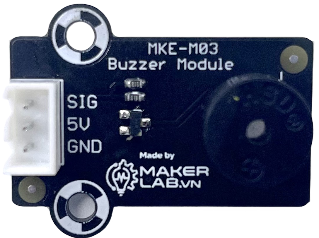
The MKE-M03 Buzzer Module is a compact and versatile electronic sound-producing device. It is designed to emit an audible tone when energized by an electrical signal. This buzzer module is widely used in various applications such as alarm systems, timers, confirmation of user input in electronic devices, and as an audible indicator for notifications.

Explore Projects Built with MKE-M03 Buzzer Module

Use Cirkit Designer to design, explore, and prototype these projects online. Some projects support real-time simulation. Click "Open Project" to start designing instantly!
Voice-Controlled Buzzer System with VC-02 Module
Image of vc: A project utilizing MKE-M03 Buzzer Module in a practical application
This circuit features a VC-02 voice recognition module connected to a buzzer and powered by a 5V battery. The VC-02 module is programmed to listen for specific voice commands and, upon recognizing the command 'can you make a sound', it activates the buzzer for one second. The circuit is designed for voice-activated sound generation, with the VC-02 module handling voice recognition and serial communication, and the buzzer providing audible feedback.
Cirkit Designer LogoOpen Project in Cirkit Designer
IoT-Enabled Environmental Monitoring System with NUCLEO-F303RE and ESP8266
Image of GAS LEAKAGE DETECTION: A project utilizing MKE-M03 Buzzer Module in a practical application
This circuit features a NUCLEO-F303RE microcontroller board interfaced with various modules for sensing, actuation, and communication. It includes an MQ-2 gas sensor for detecting combustible gases, a buzzer for audible alerts, and a relay for controlling high-power devices. Additionally, the circuit uses an ESP8266 WiFi module for wireless connectivity and an I2C LCD display for user interface and data display.
Cirkit Designer LogoOpen Project in Cirkit Designer
ESP32-Controlled Ultrasonic Distance Measurement with LED Feedback and Buzzer Alert System
Image of iot device: A project utilizing MKE-M03 Buzzer Module in a practical application
This circuit features an ESP32 microcontroller connected to a Grove LED bar, an HC-SR04 Ultrasonic Sensor, and a Buzzer Module. The ESP32 controls the LED bar and buzzer, and receives input from the ultrasonic sensor. A MKE-M12 5VDC 5A Power Supply Module, powered by a DC Power Source, provides regulated 5V power to the components.
Cirkit Designer LogoOpen Project in Cirkit Designer
Wi-Fi Controlled Buzzer with Wemos D1 Mini
Image of Buzzer Twinkle: A project utilizing MKE-M03 Buzzer Module in a practical application
This circuit consists of a Wemos D1 Mini microcontroller connected to an active buzzer module. The Wemos D1 Mini provides power to the buzzer and controls it through its D1 pin, allowing for programmable sound output.
Cirkit Designer LogoOpen Project in Cirkit Designer

Explore Projects Built with MKE-M03 Buzzer Module

Use Cirkit Designer to design, explore, and prototype these projects online. Some projects support real-time simulation. Click "Open Project" to start designing instantly!
Image of vc: A project utilizing MKE-M03 Buzzer Module in a practical application
Voice-Controlled Buzzer System with VC-02 Module
This circuit features a VC-02 voice recognition module connected to a buzzer and powered by a 5V battery. The VC-02 module is programmed to listen for specific voice commands and, upon recognizing the command 'can you make a sound', it activates the buzzer for one second. The circuit is designed for voice-activated sound generation, with the VC-02 module handling voice recognition and serial communication, and the buzzer providing audible feedback.
Cirkit Designer LogoOpen Project in Cirkit Designer
Image of GAS LEAKAGE DETECTION: A project utilizing MKE-M03 Buzzer Module in a practical application
IoT-Enabled Environmental Monitoring System with NUCLEO-F303RE and ESP8266
This circuit features a NUCLEO-F303RE microcontroller board interfaced with various modules for sensing, actuation, and communication. It includes an MQ-2 gas sensor for detecting combustible gases, a buzzer for audible alerts, and a relay for controlling high-power devices. Additionally, the circuit uses an ESP8266 WiFi module for wireless connectivity and an I2C LCD display for user interface and data display.
Cirkit Designer LogoOpen Project in Cirkit Designer
Image of iot device: A project utilizing MKE-M03 Buzzer Module in a practical application
ESP32-Controlled Ultrasonic Distance Measurement with LED Feedback and Buzzer Alert System
This circuit features an ESP32 microcontroller connected to a Grove LED bar, an HC-SR04 Ultrasonic Sensor, and a Buzzer Module. The ESP32 controls the LED bar and buzzer, and receives input from the ultrasonic sensor. A MKE-M12 5VDC 5A Power Supply Module, powered by a DC Power Source, provides regulated 5V power to the components.
Cirkit Designer LogoOpen Project in Cirkit Designer
Image of Buzzer Twinkle: A project utilizing MKE-M03 Buzzer Module in a practical application
Wi-Fi Controlled Buzzer with Wemos D1 Mini
This circuit consists of a Wemos D1 Mini microcontroller connected to an active buzzer module. The Wemos D1 Mini provides power to the buzzer and controls it through its D1 pin, allowing for programmable sound output.
Cirkit Designer LogoOpen Project in Cirkit Designer

Common Applications

  • Alarm systems
  • Electronic toys
  • Timers and stopwatches
  • User input feedback for devices
  • Notification systems in appliances

Technical Specifications

The following table outlines the key technical specifications of the MKE-M03 Buzzer Module:

Specification Value Description
Operating Voltage 3.3V - 5V The voltage range within which the buzzer operates safely.
Rated Current 30mA The current consumption at the rated voltage.
Sound Output ≥85dB Minimum sound output level at 10cm distance.
Resonant Frequency 2300Hz ± 300Hz The frequency at which the buzzer naturally oscillates.
Tone Continuous The type of sound emitted when powered.
Drive Type Passive (requires an external signal) The buzzer needs an external signal to produce sound.

Pin Configuration

Pin Description
VCC Power supply (3.3V - 5V)
GND Ground connection
SIG Signal input, controls the buzzer

Usage Instructions

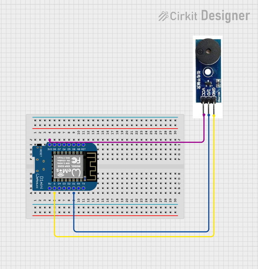
Connecting to a Circuit

  1. Connect the VCC pin of the MKE-M03 Buzzer Module to the positive supply voltage (3.3V - 5V).
  2. Connect the GND pin to the ground of the power supply.
  3. The SIG pin is used to control the buzzer. Connect this to a digital output pin on a microcontroller, such as an Arduino UNO.

Best Practices

  • Do not exceed the recommended voltage as it may damage the buzzer.
  • Use a current-limiting resistor if operating at a voltage significantly lower than the rated voltage to prevent insufficient sound output.
  • Avoid continuous operation at high sound levels to prolong the lifespan of the buzzer.

Example Code for Arduino UNO

// Define the buzzer control pin
const int buzzerPin = 8;

void setup() {
  // Set the buzzer pin as an output
  pinMode(buzzerPin, OUTPUT);
}

void loop() {
  // Turn on the buzzer
  digitalWrite(buzzerPin, HIGH);
  delay(1000); // Buzzer on for 1 second
  
  // Turn off the buzzer
  digitalWrite(buzzerPin, LOW);
  delay(1000); // Buzzer off for 1 second
}

This simple Arduino sketch toggles the buzzer on and off every second. The digitalWrite function sends a HIGH or LOW signal to the buzzer, which turns it on or off, respectively.

Troubleshooting and FAQs

Common Issues

  • Buzzer not sounding: Ensure that the connections are correct and secure. Check the power supply voltage and signal input.
  • Low sound output: Verify that the operating voltage is within the specified range and that the current is not limited excessively by a resistor.
  • Intermittent sound: Check for loose connections or intermittent signals from the control source.

FAQs

Q: Can I use the MKE-M03 Buzzer Module with a 3.3V system?

A: Yes, the buzzer can operate within a 3.3V - 5V range, making it suitable for both 3.3V and 5V systems.

Q: Does the buzzer require a PWM signal to operate?

A: No, the MKE-M03 is a passive buzzer and can be operated with a simple digital HIGH/LOW signal. However, you can use PWM to create different tones.

Q: Is it possible to adjust the volume of the buzzer?

A: The volume is not directly adjustable. It is determined by the input voltage and the design of the buzzer. However, you can indirectly affect the perceived volume by changing the distance or enclosure around the buzzer.

For further assistance or inquiries, please contact the manufacturer or your local distributor.