How to Use USB male 2 pin connection: Examples, Pinouts, and Specs
Introduction
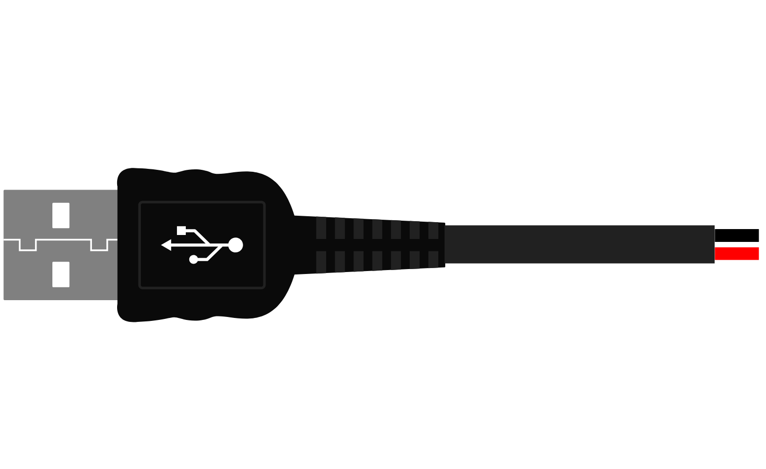
- A USB male 2 pin connection is a type of electrical connector used to establish a power and/or data link between devices. It is a simplified version of the standard USB connector, typically featuring only two pins: one for power (VCC) and one for ground (GND). This design is often used in applications where data transmission is not required, or where minimal wiring is preferred.
- Common applications include powering small electronic devices, charging batteries, and connecting to USB power sources such as wall adapters, power banks, or computers.
Explore Projects Built with USB male 2 pin connection


Explore Projects Built with USB male 2 pin connection
Technical Specifications
- Connector Type: USB Male (2 Pin)
- Voltage Rating: 5V DC (standard USB voltage)
- Current Rating: Up to 2A (depending on the cable and device specifications)
- Pin Count: 2 (VCC and GND)
- Material: Typically plastic housing with metal contacts
- Compatibility: USB Type-A ports (commonly found on computers, chargers, and power banks)
Pin Configuration and Descriptions
| Pin Number | Name | Description | Notes |
|---|---|---|---|
| 1 | VCC | Power supply (5V DC) | Provides power to the device. |
| 2 | GND | Ground | Completes the circuit. |
Usage Instructions
How to Use the Component in a Circuit
- Identify the Pins: Locate the VCC and GND pins on the USB male 2 pin connector. These are typically marked or can be identified using a multimeter.
- Connect to Power Source:
- Connect the VCC pin to the positive terminal of your power source (e.g., USB port or power adapter).
- Connect the GND pin to the negative terminal or ground.
- Connect to the Device: Ensure the device being powered is compatible with a 5V DC input and does not exceed the current rating of the USB source.
- Secure the Connections: Use soldering or a reliable connector to ensure a stable and secure connection.
Important Considerations and Best Practices
- Voltage Compatibility: Ensure the device being powered is designed to operate at 5V DC. Using a higher voltage can damage the device.
- Current Limitations: Verify that the USB power source can supply sufficient current for your device. Exceeding the current rating may cause the power source to shut down or overheat.
- Polarity: Double-check the polarity of your connections (VCC and GND) to avoid damaging the device.
- Insulation: Properly insulate all connections to prevent short circuits.
Example: Connecting to an Arduino UNO
The USB male 2 pin connection can be used to power an Arduino UNO via its 5V and GND pins. Below is an example of how to connect it:
- Connect the VCC pin of the USB male connector to the 5V pin on the Arduino UNO.
- Connect the GND pin of the USB male connector to the GND pin on the Arduino UNO.
Arduino Code Example
While the USB male 2 pin connection is typically used for power, you can use the Arduino UNO to verify the power connection by blinking an LED:
// Simple LED Blink Example
// This code assumes an LED is connected to pin 13 on the Arduino UNO.

void setup() {
  pinMode(13, OUTPUT); // Set pin 13 as an output
}

void loop() {
  digitalWrite(13, HIGH); // Turn the LED on
  delay(1000);            // Wait for 1 second
  digitalWrite(13, LOW);  // Turn the LED off
  delay(1000);            // Wait for 1 second
}
Troubleshooting and FAQs
Common Issues Users Might Face
Device Not Powering On:
- Cause: Incorrect wiring or insufficient power supply.
- Solution: Verify the VCC and GND connections. Ensure the power source provides adequate voltage and current.
Overheating Connector:
- Cause: Excessive current draw or poor-quality connector.
- Solution: Check the current requirements of the device. Use a connector rated for higher current if necessary.
Short Circuit:
- Cause: Exposed wires or incorrect connections.
- Solution: Inspect all connections for exposed wires or solder bridges. Insulate connections properly.
Intermittent Power Loss:
- Cause: Loose connections or damaged cable.
- Solution: Ensure all connections are secure. Replace the cable if it is damaged.
FAQs
Q: Can I use this connector for data transmission?
A: No, the USB male 2 pin connection is designed only for power delivery. For data transmission, a 4-pin USB connector is required.Q: What happens if I reverse the VCC and GND connections?
A: Reversing the connections can damage your device. Always double-check the polarity before powering the circuit.Q: Can I use this connector with a USB Type-C port?
A: Yes, but you will need an adapter or cable that converts USB Type-C to USB Type-A.Q: Is this connector suitable for high-power devices?
A: No, this connector is typically rated for up to 2A. For higher power requirements, consider using a connector with a higher current rating.
This concludes the documentation for the USB male 2 pin connection.