How to Use LM393: Examples, Pinouts, and Specs
Introduction
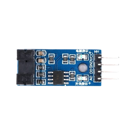
The LM393 is a versatile dual voltage comparator that contains two independent precision voltage comparators. It is designed to operate from a single power supply over a wide range of voltages, making it a popular choice for various applications. Common uses include threshold detection, overvoltage protection, and waveform shaping. Its ability to compare two input voltages and provide a digital output makes it suitable for creating simple analog-to-digital interfaces.
Explore Projects Built with LM393
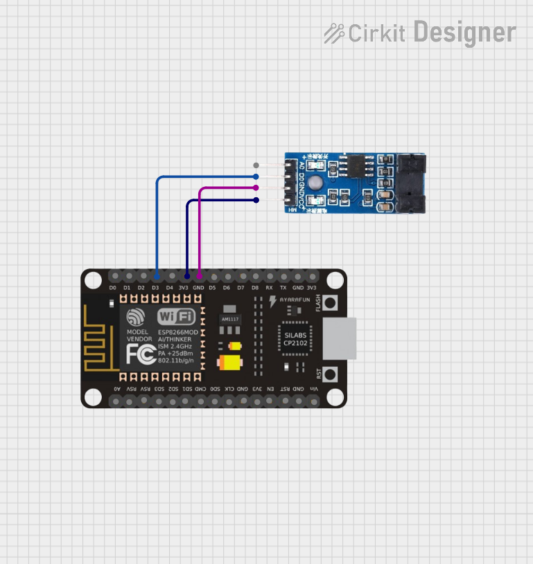
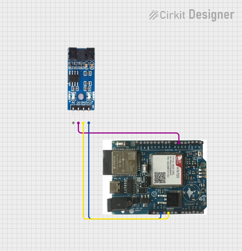


Explore Projects Built with LM393
Technical Specifications
Key Technical Details
- Supply Voltage Range: 2.0V to 36V (or ±1.0V to ±18V)
- Input Offset Voltage: 5mV max (at 25°C)
- Input Bias Current: 25nA (typical)
- Output Current: 20mA (typical)
- Response Time: 1.3μs (typical)
- Operating Temperature Range: 0°C to 70°C
Pin Configuration and Descriptions
| Pin Number | Name | Description |
|---|---|---|
| 1 | OUT1 | Output of comparator 1 |
| 2 | IN1- | Inverting input of comparator 1 |
| 3 | IN1+ | Non-inverting input of comparator 1 |
| 4 | GND | Ground (0V) reference |
| 5 | IN2+ | Non-inverting input of comparator 2 |
| 6 | IN2- | Inverting input of comparator 2 |
| 7 | OUT2 | Output of comparator 2 |
| 8 | VCC | Positive supply voltage |
Usage Instructions
How to Use the LM393 in a Circuit
- Power Supply: Connect the VCC pin to a positive supply voltage within the range of 2.0V to 36V and the GND pin to the ground of the circuit.
- Input Signals: Apply the analog signals to be compared to the IN+ and IN- pins of the respective comparator.
- Output Connection: Connect the OUT pin to a digital input of a microcontroller or to an LED with a current-limiting resistor to visualize the comparator's output.
Important Considerations and Best Practices
- Ensure that the supply voltage does not exceed the maximum rating to prevent damage.
- Use bypass capacitors near the power supply pins to minimize noise.
- Avoid applying input voltages that exceed the supply voltage range.
- When interfacing with a microcontroller, ensure that the output voltage levels are compatible.
Example Connection with Arduino UNO
// Define the Arduino pin connected to the LM393 output
const int comparatorOutputPin = 2;

void setup() {
  // Set the comparator output pin as an input
  pinMode(comparatorOutputPin, INPUT);
  // Begin serial communication at 9600 baud rate
  Serial.begin(9600);
}

void loop() {
  // Read the state of the comparator output
  int comparatorState = digitalRead(comparatorOutputPin);
  // Print the state to the Serial Monitor
  Serial.println(comparatorState);
  // A short delay before the next reading
  delay(500);
}
Troubleshooting and FAQs
Common Issues
- No Output Signal: Ensure that the power supply is connected correctly and the input signals are within the expected range.
- Erratic Output: Check for loose connections and ensure that the input signals are not too noisy. Use bypass capacitors if necessary.
- Output Always High or Low: Verify that the input signals are crossing the threshold as expected and that the supply voltage is adequate.
Solutions and Tips for Troubleshooting
- Double-check wiring and solder joints for any potential issues.
- Use an oscilloscope to observe the input signals and the output of the comparator.
- Ensure that the power supply is stable and within the specified range.
FAQs
Q: Can the LM393 operate with different voltages on each comparator? A: No, both comparators share the same power supply pins and thus operate at the same voltage.
Q: Is it necessary to use both comparators in the LM393? A: No, you can use one comparator without affecting the functionality of the other.
Q: Can the LM393 outputs drive LEDs directly? A: Yes, but ensure to use a current-limiting resistor to protect the LED and the LM393 output stage.
Q: What is the purpose of the LM393's open-collector output? A: The open-collector output allows for voltage level shifting and the ability to connect multiple outputs together for a wired-AND configuration.
Please note that the LM393 is not an Arduino-manufactured component, but it is commonly used with Arduino and other microcontroller platforms. The part ID WPSE347 is a generic identifier and may not correspond to a specific manufacturer's part number. Always refer to the datasheet of the specific LM393 you are using for the most accurate information.