How to Use MyoWare Muscle Sensor 1.0: Examples, Pinouts, and Specs
Introduction
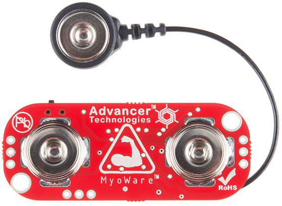
The MyoWare Muscle Sensor 1.0 is a compact and versatile device designed to detect electrical activity in muscles, enabling the measurement of muscle contractions. By leveraging electromyography (EMG) technology, this sensor translates muscle activity into an analog signal that can be used in various applications. It is widely utilized in biofeedback systems, prosthetics, robotics, and other projects requiring muscle-based control.
Explore Projects Built with MyoWare Muscle Sensor 1.0
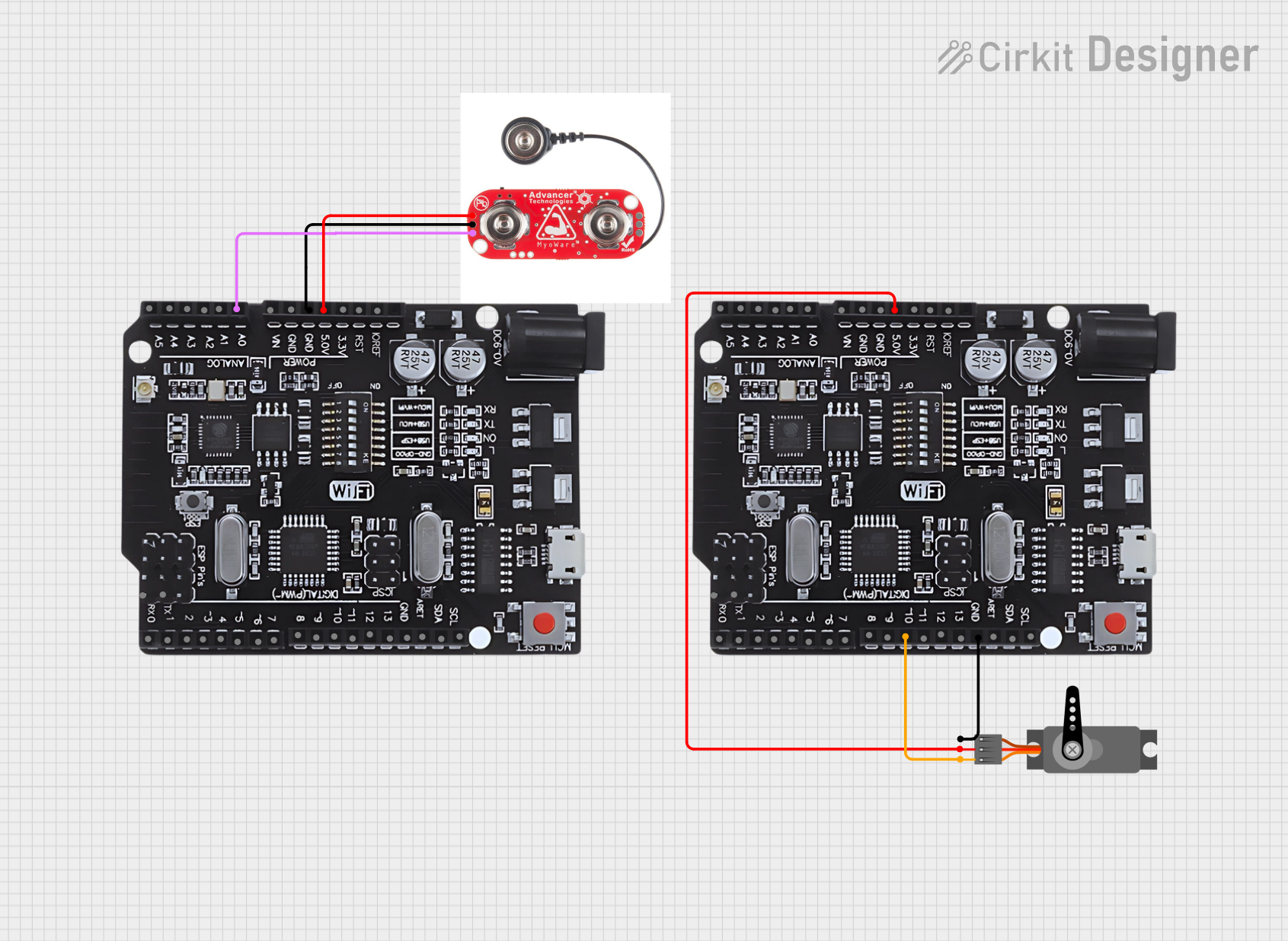
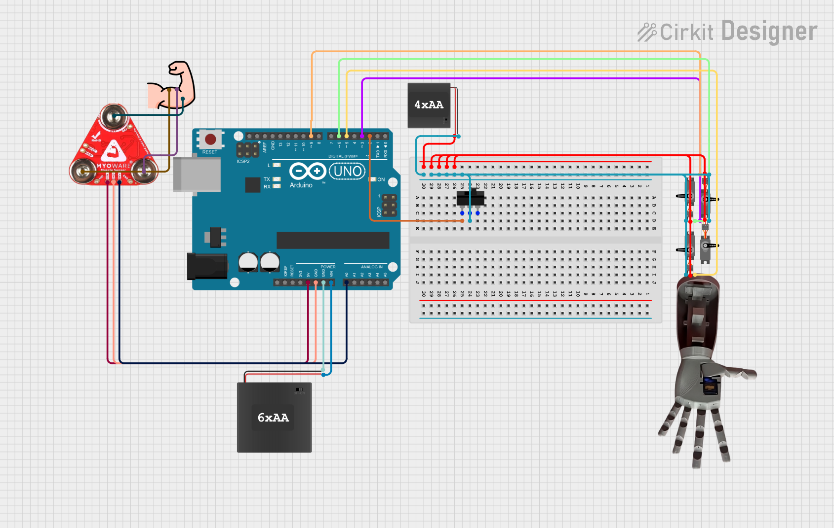
Explore Projects Built with MyoWare Muscle Sensor 1.0
Common Applications and Use Cases
- Biofeedback Systems: Monitor muscle activity for rehabilitation or fitness tracking.
- Prosthetics: Enable control of prosthetic limbs using muscle signals.
- Robotics: Control robotic systems or devices based on muscle movements.
- Wearable Technology: Integrate into wearable devices for gesture recognition or health monitoring.
- Gaming and VR: Use muscle signals for interactive gaming or virtual reality experiences.
Technical Specifications
The MyoWare Muscle Sensor 1.0 is designed for ease of use and compatibility with microcontrollers like Arduino. Below are its key technical details:
Key Technical Details
- Operating Voltage: 3.1V to 5.5V
- Output Signal: Analog (0V to Vcc)
- Current Consumption: ~9mA
- Input Impedance: >1MΩ
- Gain: Adjustable via onboard potentiometer
- Electrode Connector: Snap-style for standard EMG electrodes
- Dimensions: 1.0" x 1.0" (25.4mm x 25.4mm)
Pin Configuration and Descriptions
The MyoWare Muscle Sensor 1.0 has a simple pinout for easy integration into circuits:
| Pin Name | Type | Description |
|---|---|---|
RAW |
Analog Output | Outputs the raw EMG signal (unfiltered, unrectified). |
SIG |
Analog Output | Outputs the processed EMG signal (filtered and rectified). |
+ |
Power Input | Connect to the positive supply voltage (3.1V to 5.5V). |
- |
Ground | Connect to the ground of the power supply. |
REF |
Reference Pin | Optional reference voltage input for differential measurements (default: GND). |
Usage Instructions
The MyoWare Muscle Sensor 1.0 is straightforward to use in a circuit. Follow these steps to integrate it into your project:
Connecting the Sensor
- Attach Electrodes: Snap three standard EMG electrodes onto the sensor. Place the electrodes on the target muscle:
- Two electrodes on the muscle belly (active electrodes).
- One electrode on a bony or non-muscular area (reference electrode).
- Connect to Power: Supply 3.1V to 5.5V to the
+pin and connect the-pin to ground. - Read the Signal: Use the
SIGpin for the processed EMG signal or theRAWpin for the unprocessed signal.
Important Considerations
- Electrode Placement: Proper placement of electrodes is critical for accurate readings. Ensure the skin is clean and free of oils.
- Signal Noise: Minimize noise by avoiding movement artifacts and ensuring good electrode contact.
- Power Supply: Use a stable power source to prevent fluctuations in the output signal.
- Microcontroller Compatibility: The sensor is compatible with most microcontrollers, including Arduino, Raspberry Pi, and others.
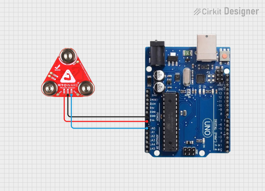
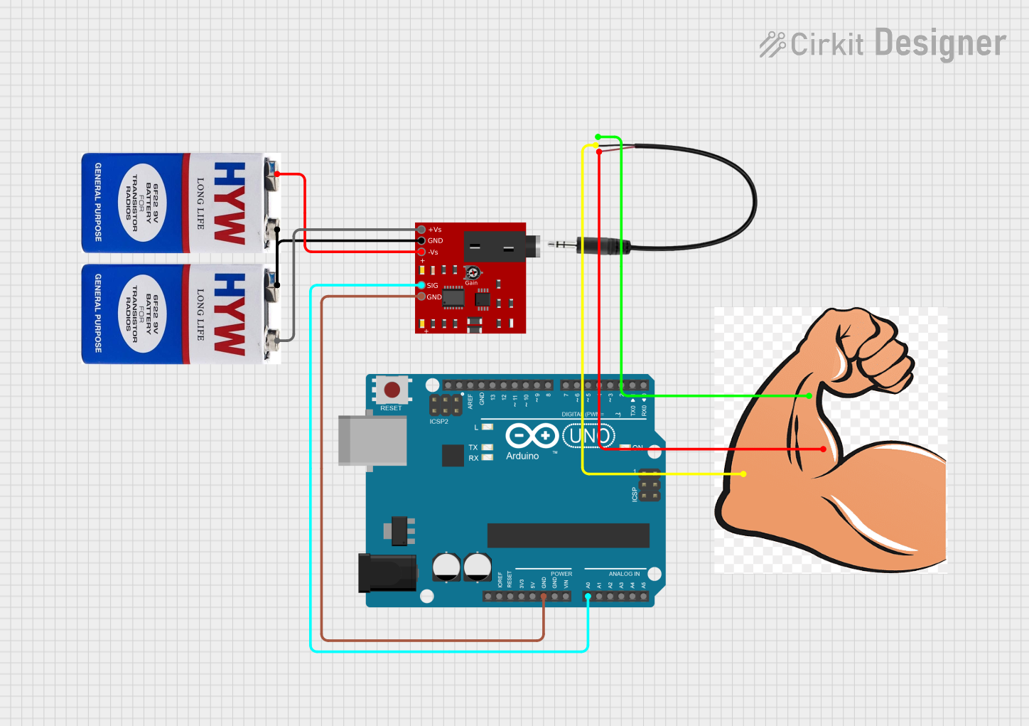
Example: Using with Arduino UNO
Below is an example of how to connect and read data from the MyoWare Muscle Sensor 1.0 using an Arduino UNO:
Circuit Diagram
- Connect the
+pin to the Arduino's5Vpin. - Connect the
-pin to the Arduino'sGNDpin. - Connect the
SIGpin to an analog input pin on the Arduino (e.g.,A0).
Arduino Code
// MyoWare Muscle Sensor 1.0 Example Code
// Reads the processed EMG signal from the SIG pin and prints it to the Serial Monitor.

const int muscleSensorPin = A0; // Analog pin connected to SIG pin of the sensor

void setup() {
  Serial.begin(9600); // Initialize serial communication at 9600 baud
  pinMode(muscleSensorPin, INPUT); // Set the sensor pin as input
}

void loop() {
  int sensorValue = analogRead(muscleSensorPin); // Read the analog value from the sensor
  Serial.print("Muscle Signal: ");
  Serial.println(sensorValue); // Print the value to the Serial Monitor
  delay(10); // Small delay for stability
}
Best Practices
- Use shielded cables to reduce electromagnetic interference.
- Calibrate the sensor for your specific application by adjusting the onboard potentiometer.
- Avoid placing the sensor near high-power devices or motors to minimize noise.
Troubleshooting and FAQs
Common Issues and Solutions
No Signal Detected
- Ensure the electrodes are properly attached to the skin and the sensor.
- Verify that the power supply is within the specified range (3.1V to 5.5V).
- Check the connections between the sensor and the microcontroller.
Noisy or Unstable Signal
- Ensure the skin is clean and dry before attaching electrodes.
- Use shielded cables and avoid running wires near high-power devices.
- Adjust the gain using the onboard potentiometer.
Low Signal Amplitude
- Verify proper electrode placement on the muscle belly.
- Increase the gain using the potentiometer if necessary.
Arduino Not Reading Data
- Confirm that the
SIGpin is connected to the correct analog input pin. - Check the Arduino code for errors and ensure the correct pin is defined.
- Confirm that the
FAQs
Q: Can I use the MyoWare Muscle Sensor 1.0 with a battery-powered system?
A: Yes, the sensor can be powered by a battery as long as the voltage is within the 3.1V to 5.5V range.
Q: What type of electrodes should I use?
A: Use standard snap-style EMG electrodes for optimal performance.
Q: Can I use multiple sensors simultaneously?
A: Yes, you can use multiple sensors, but ensure proper grounding and avoid crosstalk by spacing the sensors appropriately.
Q: Is the sensor safe for prolonged use?
A: Yes, the sensor is designed for safe use, but avoid prolonged use on sensitive skin to prevent irritation.
By following this documentation, you can effectively integrate the MyoWare Muscle Sensor 1.0 into your projects and troubleshoot common issues.