The Neo-6m V2, manufactured by Ublox, is a high-performance GPS module designed to provide accurate positioning and navigation data. It features a built-in ceramic antenna, low power consumption, and compatibility with multiple satellite systems, including GPS, SBAS (WAAS, EGNOS, MSAS), and QZSS. This module is widely used in applications such as vehicle tracking, drones, robotics, and other location-based services.
Explore Projects Built with Neo-6m V2
Use Cirkit Designer to design, explore, and prototype these projects online. Some projects support real-time simulation. Click "Open Project" to start designing instantly!
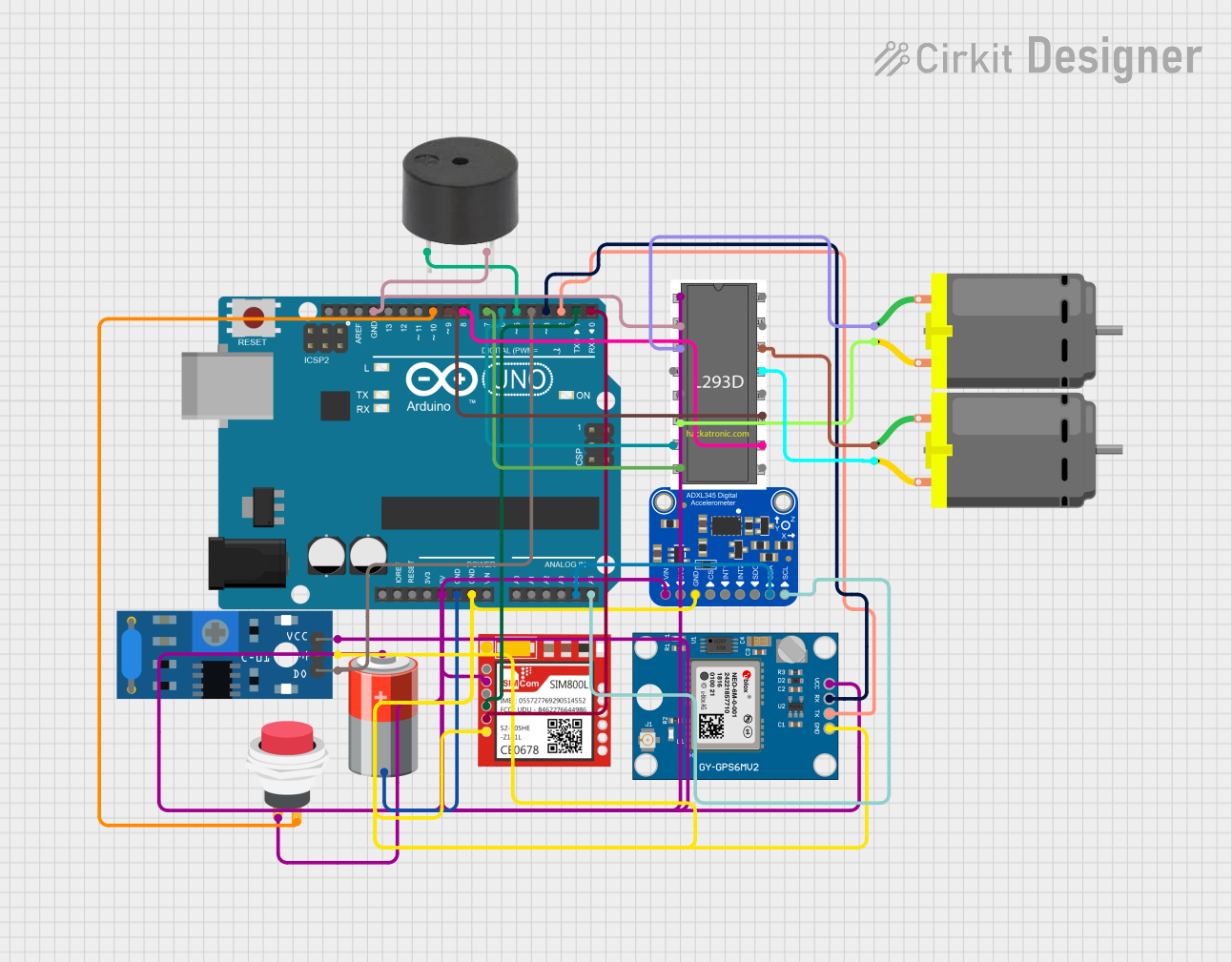
This circuit is a GPS-based tracking system with vibration detection and motor control capabilities. It uses an Arduino UNO to interface with a Neo 6M GPS module for location data, a Sim800l module for GSM communication, an ADXL345 accelerometer for motion sensing, and an SW-420 vibration sensor to detect vibrations. The system also includes a motor driver to control two DC motors and a buzzer for alerts, all powered by a 5V battery.
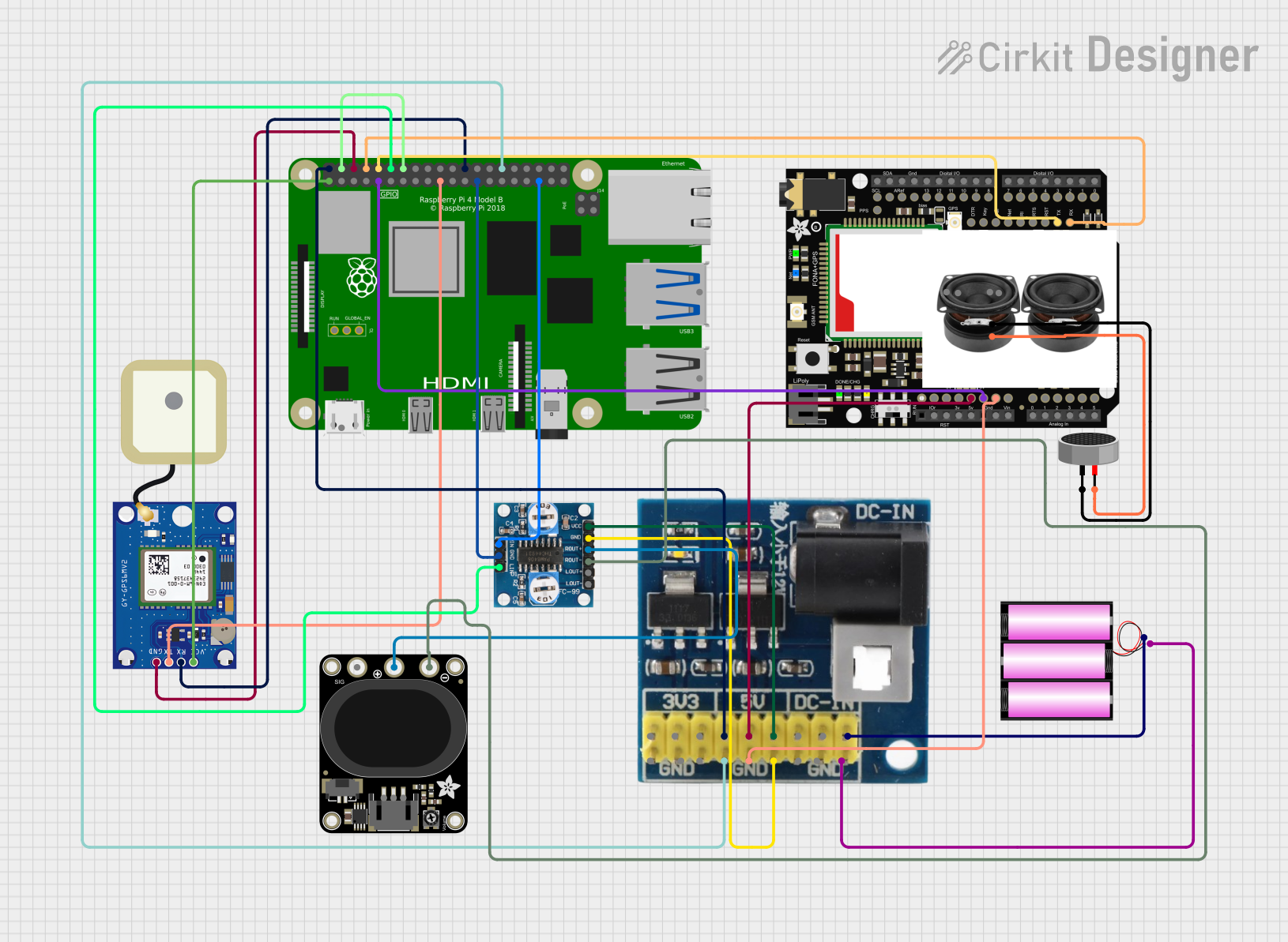
This circuit features a Raspberry Pi 4B as the central processing unit, interfaced with a GPS NEO-6M V2 module for location tracking and an Adafruit FONA 808 Shield for cellular communication. It includes a PAM8406 5V Digital Audio Amplifier connected to an Adafruit STEMMA Speaker for audio output, and a Condenser Microphone connected to the FONA 808 for audio input. Power management is handled by a 12V battery connected to a voltage regulator that steps down the voltage to 5V and 3V required by the various components.
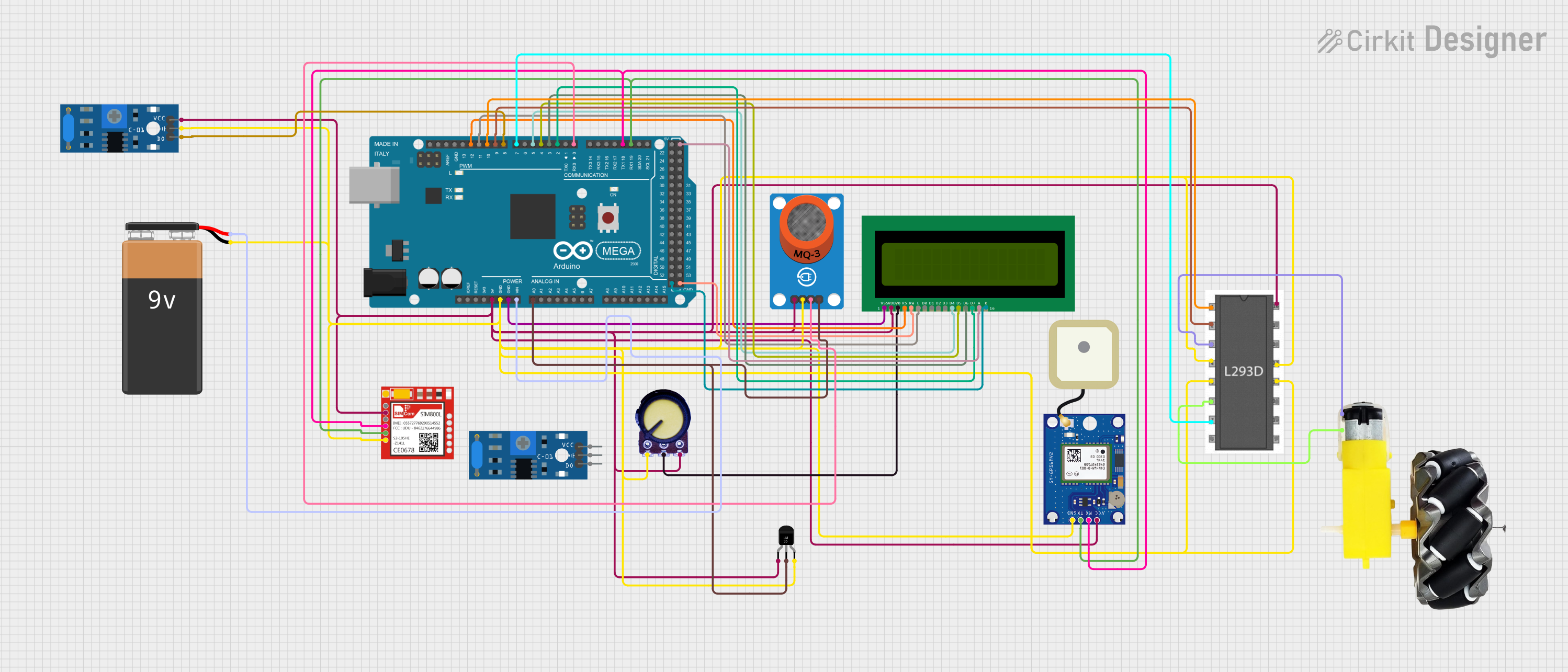
This is a sensor-rich embedded system with communication and display capabilities, designed for monitoring environmental parameters and controlling motors. It integrates alcohol and temperature sensors, vibration detection, GPS tracking, GSM communication, and an LCD for output, all managed by an Arduino Mega 2560.
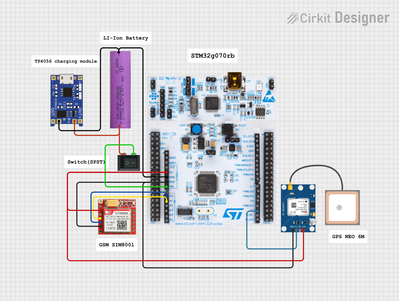
This circuit is an emergency alert system that uses a NUCLEO-F072RB microcontroller to send SMS alerts and make calls via a SIM800L GSM module, while obtaining location data from a GPS NEO 6M module. The system is powered by a Li-ion battery and includes a TP4056 module for battery charging and protection, with a rocker switch to control power to the microcontroller.
Below are the key technical details and pin configuration of the Neo-6m V2 GPS module:
Key Technical Details:
Parameter
Specification
Manufacturer
Ublox
Part Number
Neo-6m V2
Input Voltage
2.7V to 3.6V (typically 3.3V)
Power Consumption
~45mA (active mode)
Positioning Accuracy
2.5 meters CEP (Circular Error Probable)
Cold Start Time
< 27 seconds
Hot Start Time
< 1 second
Update Rate
1 Hz (default), configurable up to 5 Hz
Communication Interface
UART (default), SPI, I2C
Operating Temperature
-40°C to +85°C
Dimensions
16 x 12.2 x 2.4 mm
Pin Configuration:
The Neo-6m V2 module typically comes with a breakout board for easier integration. Below is the pinout description:
Pin Name
Pin Number
Description
VCC
1
Power supply input (3.3V recommended)
GND
2
Ground
TXD
3
UART Transmit (data output)
RXD
4
UART Receive (data input)
PPS
5
Pulse Per Second (timing signal output)
SDA
6
I2C Data (optional, not always used)
SCL
7
I2C Clock (optional, not always used)
Usage Instructions
How to Use the Neo-6m V2 in a Circuit:
Power Supply: Connect the VCC pin to a 3.3V power source and the GND pin to ground.
UART Communication: Connect the TXD pin of the module to the RX pin of your microcontroller (e.g., Arduino UNO) and the RXD pin of the module to the TX pin of the microcontroller.
Antenna: Ensure the built-in ceramic antenna has a clear view of the sky for optimal satellite reception. For indoor use, an external active antenna may be required.
PPS Signal: If precise timing is needed, connect the PPS pin to a GPIO pin on your microcontroller.
Important Considerations:
Power Supply: Use a stable 3.3V power source to avoid damaging the module.
Antenna Placement: Place the module in an open area with minimal obstructions for better GPS signal reception.
Baud Rate: The default UART baud rate is 9600 bps. Ensure your microcontroller is configured to match this rate.
Backup Battery: Some breakout boards include a battery for faster hot starts. Ensure the battery is functional for optimal performance.
Example Code for Arduino UNO:
Below is an example of how to interface the Neo-6m V2 with an Arduino UNO using the SoftwareSerial library:
#include <SoftwareSerial.h>

// Define RX and TX pins for SoftwareSerial
SoftwareSerial gpsSerial(4, 3); // RX = Pin 4, TX = Pin 3

void setup() {
  Serial.begin(9600); // Initialize Serial Monitor at 9600 baud
  gpsSerial.begin(9600); // Initialize GPS module at 9600 baud

  Serial.println("Neo-6m V2 GPS Module Test");
}

void loop() {
  // Check if data is available from the GPS module
  while (gpsSerial.available()) {
    char c = gpsSerial.read(); // Read one character from GPS
    Serial.print(c); // Print the character to the Serial Monitor
  }
}
Notes:
Connect the GPS module's TXD pin to Arduino's Pin 4 and RXD pin to Arduino's Pin 3.
Open the Serial Monitor to view the GPS data in NMEA format (e.g., GPGGA, GPRMC sentences).
Troubleshooting and FAQs
Common Issues and Solutions:
No GPS Fix (No Satellite Lock):
Cause: Poor antenna placement or indoor use.
Solution: Move the module to an open area with a clear view of the sky. Use an external active antenna if necessary.
No Data Output:
Cause: Incorrect wiring or baud rate mismatch.
Solution: Double-check the connections and ensure the UART baud rate is set to 9600 bps.
Intermittent Data Loss:
Cause: Unstable power supply.
Solution: Use a regulated 3.3V power source and ensure proper grounding.
PPS Signal Not Working:
Cause: PPS pin not connected or misconfigured.
Solution: Verify the PPS pin connection and configure your microcontroller to read the signal.
FAQs:
Q: Can the Neo-6m V2 work indoors?
A: The module may work indoors near windows, but signal quality will be reduced. Use an external active antenna for better performance.
Q: How do I increase the update rate?
A: Use Ublox's u-center software to configure the module's update rate up to 5 Hz.
Q: What is the default communication protocol?
A: The default protocol is UART with a baud rate of 9600 bps.
Q: Can I use the Neo-6m V2 with a 5V microcontroller?
A: Yes, but you must use a level shifter to step down the 5V signals to 3.3V to avoid damaging the module.
This concludes the documentation for the Neo-6m V2 GPS module.


 Open Project in Cirkit Designer