Cirkit Designer Logo
Cirkit Designer
Your all-in-one circuit design IDE
Home / 
Component Documentation

How to Use Adafruit Charlieplex 9x16 Red: Examples, Pinouts, and Specs

Image of Adafruit Charlieplex 9x16 Red
Cirkit Designer LogoDesign with Adafruit Charlieplex 9x16 Red in Cirkit Designer

Introduction

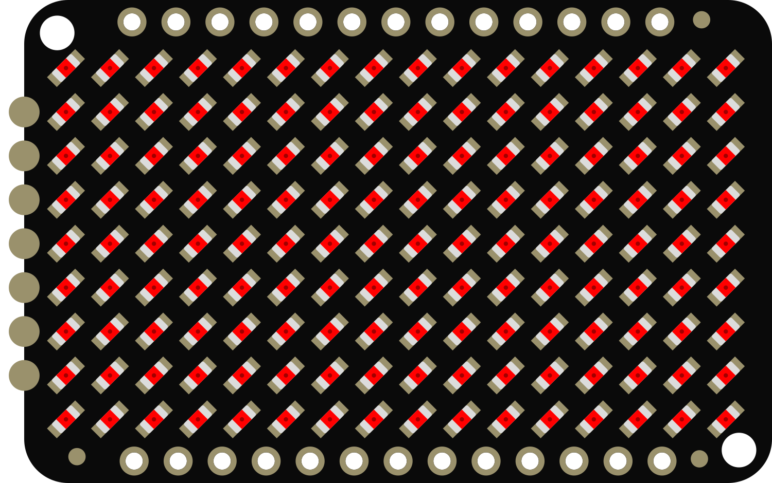
The Adafruit Charlieplex 9x16 Red is a versatile and compact LED matrix display that leverages the charlieplexing technique to control 144 red LEDs using a minimal number of microcontroller pins. This matrix is ideal for creating eye-catching displays for alphanumeric characters, simple graphics, and animations. Its small form factor makes it perfect for wearable electronics, small handheld devices, and any project where space is at a premium.

Explore Projects Built with Adafruit Charlieplex 9x16 Red

Use Cirkit Designer to design, explore, and prototype these projects online. Some projects support real-time simulation. Click "Open Project" to start designing instantly!
Arduino UNO Controlled RGB LED Matrix with Bluetooth Connectivity and Audio Output
Image of the bell : A project utilizing Adafruit Charlieplex 9x16 Red in a practical application
This is an interactive display and communication circuit. It uses an Arduino UNO to drive multiple WS2812 RGB LED matrices for visual output, interfaces with a DS3231 RTC for time-related functions, and communicates wirelessly via an HC-05 Bluetooth module. Additionally, it features audio output capabilities through a speaker connected to a PAM8403 audio amplifier.
Cirkit Designer LogoOpen Project in Cirkit Designer
Arduino UNO Controlled Multi-Matrix LED Display
Image of Test matrix with pixel moving: A project utilizing Adafruit Charlieplex 9x16 Red in a practical application
This circuit consists of an Arduino UNO microcontroller connected to multiple MAX7219 8x8 LED Matrix modules arranged in a daisy-chain configuration. The Arduino controls the LED matrices using a software-implemented SPI communication protocol, with the purpose of displaying complex patterns or animations across the combined matrix display. The provided code handles the initialization and updating of the LED matrices, creating visual effects by manipulating the framebuffer and sending the data to the LED matrices in the correct order.
Cirkit Designer LogoOpen Project in Cirkit Designer
Arduino UNO-Based Interactive LED Game with 8x8 Matrix and TM1637 Display
Image of Gra_na_refleks: A project utilizing Adafruit Charlieplex 9x16 Red in a practical application
This circuit is a game system controlled by an Arduino UNO, featuring an 8x8 LED matrix, a 4x4 keypad, and a TM1637 4-digit display. The user interacts with the game via the keypad, and the game state is displayed on the LED matrix and the TM1637 display, with power supplied by a 9V battery.
Cirkit Designer LogoOpen Project in Cirkit Designer
ESP32-Controlled Dual 8x8 LED Matrix Display with NTP Time Synchronization
Image of time: A project utilizing Adafruit Charlieplex 9x16 Red in a practical application
This circuit features an ESP32 microcontroller connected to two cascaded 8x8 LED matrix displays, powered by a 3.3V battery. The ESP32 drives the displays to show time and other information, with the code indicating functionality for connecting to WiFi, synchronizing time via NTP, and displaying data on the matrices using custom fonts. Additionally, there is a separate 3.3V battery powering a red LED, which appears to function as a simple indicator light.
Cirkit Designer LogoOpen Project in Cirkit Designer

Explore Projects Built with Adafruit Charlieplex 9x16 Red

Use Cirkit Designer to design, explore, and prototype these projects online. Some projects support real-time simulation. Click "Open Project" to start designing instantly!
Image of the bell : A project utilizing Adafruit Charlieplex 9x16 Red in a practical application
Arduino UNO Controlled RGB LED Matrix with Bluetooth Connectivity and Audio Output
This is an interactive display and communication circuit. It uses an Arduino UNO to drive multiple WS2812 RGB LED matrices for visual output, interfaces with a DS3231 RTC for time-related functions, and communicates wirelessly via an HC-05 Bluetooth module. Additionally, it features audio output capabilities through a speaker connected to a PAM8403 audio amplifier.
Cirkit Designer LogoOpen Project in Cirkit Designer
Image of Test matrix with pixel moving: A project utilizing Adafruit Charlieplex 9x16 Red in a practical application
Arduino UNO Controlled Multi-Matrix LED Display
This circuit consists of an Arduino UNO microcontroller connected to multiple MAX7219 8x8 LED Matrix modules arranged in a daisy-chain configuration. The Arduino controls the LED matrices using a software-implemented SPI communication protocol, with the purpose of displaying complex patterns or animations across the combined matrix display. The provided code handles the initialization and updating of the LED matrices, creating visual effects by manipulating the framebuffer and sending the data to the LED matrices in the correct order.
Cirkit Designer LogoOpen Project in Cirkit Designer
Image of Gra_na_refleks: A project utilizing Adafruit Charlieplex 9x16 Red in a practical application
Arduino UNO-Based Interactive LED Game with 8x8 Matrix and TM1637 Display
This circuit is a game system controlled by an Arduino UNO, featuring an 8x8 LED matrix, a 4x4 keypad, and a TM1637 4-digit display. The user interacts with the game via the keypad, and the game state is displayed on the LED matrix and the TM1637 display, with power supplied by a 9V battery.
Cirkit Designer LogoOpen Project in Cirkit Designer
Image of time: A project utilizing Adafruit Charlieplex 9x16 Red in a practical application
ESP32-Controlled Dual 8x8 LED Matrix Display with NTP Time Synchronization
This circuit features an ESP32 microcontroller connected to two cascaded 8x8 LED matrix displays, powered by a 3.3V battery. The ESP32 drives the displays to show time and other information, with the code indicating functionality for connecting to WiFi, synchronizing time via NTP, and displaying data on the matrices using custom fonts. Additionally, there is a separate 3.3V battery powering a red LED, which appears to function as a simple indicator light.
Cirkit Designer LogoOpen Project in Cirkit Designer

Common Applications and Use Cases

  • Wearable electronics
  • Message boards
  • Portable game displays
  • Battery-powered signs
  • Educational projects to demonstrate charlieplexing

Technical Specifications

Key Technical Details

  • LED Color: Red
  • Matrix Size: 9 columns x 16 rows
  • Number of LEDs: 144
  • Operating Voltage: 3.3V - 5V
  • Max Current per LED: 20mA
  • Communication: I2C interface

Pin Configuration and Descriptions

Pin Number Name Description
1 GND Ground connection
2 VCC Power supply (3.3V - 5V)
3 SDA I2C Data line
4 SCL I2C Clock line
5 ADDR I2C Address selection (connect to GND or VCC)

Usage Instructions

How to Use the Component in a Circuit

  1. Power Connections: Connect the VCC pin to the power supply (3.3V or 5V) and the GND pin to the ground of your circuit.
  2. I2C Communication: Connect the SDA and SCL pins to the corresponding I2C data and clock lines on your microcontroller.
  3. Address Selection: The ADDR pin can be connected to GND or VCC to select between two I2C addresses. This allows for two matrices to be used on the same I2C bus.

Important Considerations and Best Practices

  • Ensure that the power supply voltage matches the operating voltage of the matrix.
  • Limit the current to each LED to a maximum of 20mA to prevent damage.
  • Use pull-up resistors on the I2C data and clock lines if your microcontroller does not have built-in pull-ups.
  • When displaying static images, it's recommended to use a low duty cycle to prevent LED overheating.

Example Code for Arduino UNO

#include <Wire.h>
#include <Adafruit_IS31FL3731.h>

// Create the LED driver object
Adafruit_IS31FL3731 matrix = Adafruit_IS31FL3731();

void setup() {
  Wire.begin(); // Start I2C
  matrix.begin(); // Initialize the LED matrix
}

void loop() {
  // Display a pattern on the matrix
  for (uint8_t i = 0; i < 9; i++) {
    for (uint8_t j = 0; j < 16; j++) {
      matrix.drawPixel(i, j, (i + j) % 2 ? 255 : 0); // Checkerboard pattern
    }
  }
  delay(500);
  matrix.clear(); // Clear the display
  delay(500);
}

Troubleshooting and FAQs

Common Issues

  • LEDs Not Lighting Up: Ensure that the power supply is correctly connected and within the operating voltage range. Check the I2C connections and verify that the correct I2C address is being used.
  • Dim LEDs: Confirm that the current limiting resistors are appropriate and that the power supply can deliver sufficient current.
  • Flickering Display: This may be due to a poor connection or insufficient power supply. Check all connections and ensure the power supply is stable.

Solutions and Tips for Troubleshooting

  • Double-check wiring against the pin configuration table.
  • Use a multimeter to verify the voltage at the VCC pin and the continuity of the I2C lines.
  • If using multiple matrices, ensure that each has a unique I2C address.
  • Consult the Adafruit IS31FL3731 library documentation for additional functions and examples.

FAQs

Q: Can I use more than one Charlieplex 9x16 Red matrix at a time? A: Yes, you can use two matrices on the same I2C bus by setting different addresses using the ADDR pin.

Q: How do I control individual LEDs? A: Individual LEDs can be controlled using the drawPixel function provided by the Adafruit IS31FL3731 library.

Q: What is the maximum brightness for the LEDs? A: The maximum brightness is achieved by setting the LED current to 20mA. However, for extended lifespan and reliability, it is recommended to operate at a lower current.

Q: Can I use this matrix with a 3.3V system? A: Yes, the matrix can operate at 3.3V, but ensure that the I2C logic levels are compatible with your microcontroller.