How to Use (Arm) Driver Brushed Motor Controller: Examples, Pinouts, and Specs
Introduction
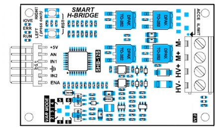
The (Arm) Driver Brushed Motor Controller, manufactured by Robot Shop with the part ID CCS_SHB12S, is an electronic device designed to control brushed DC motors commonly used in robotics applications. This controller is particularly suitable for driving robot arms and various actuators, providing precise control over speed and direction.
Explore Projects Built with (Arm) Driver Brushed Motor Controller
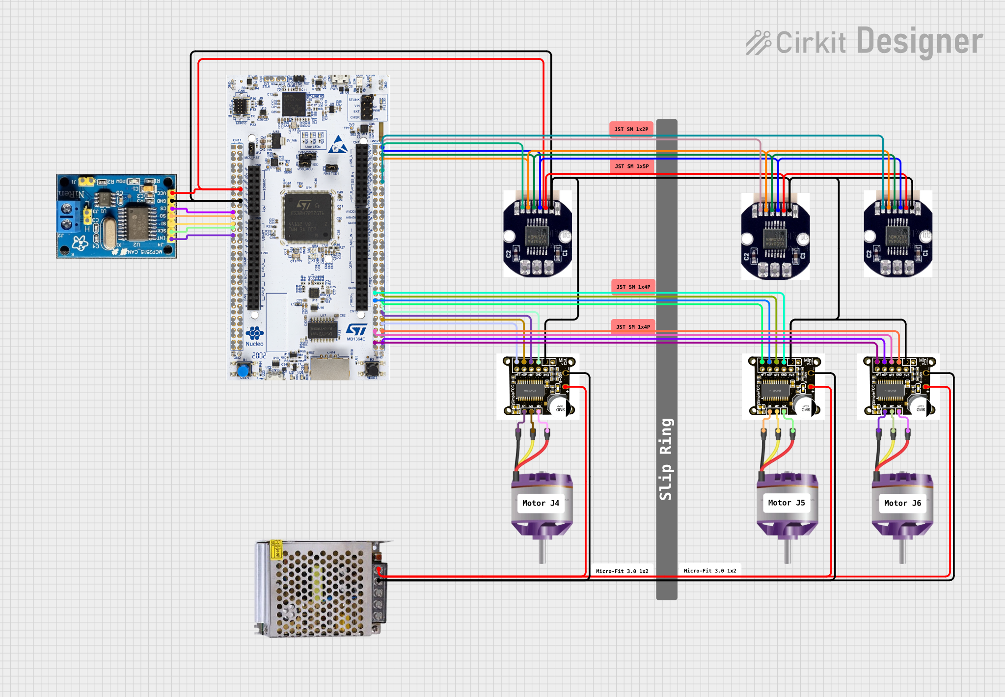
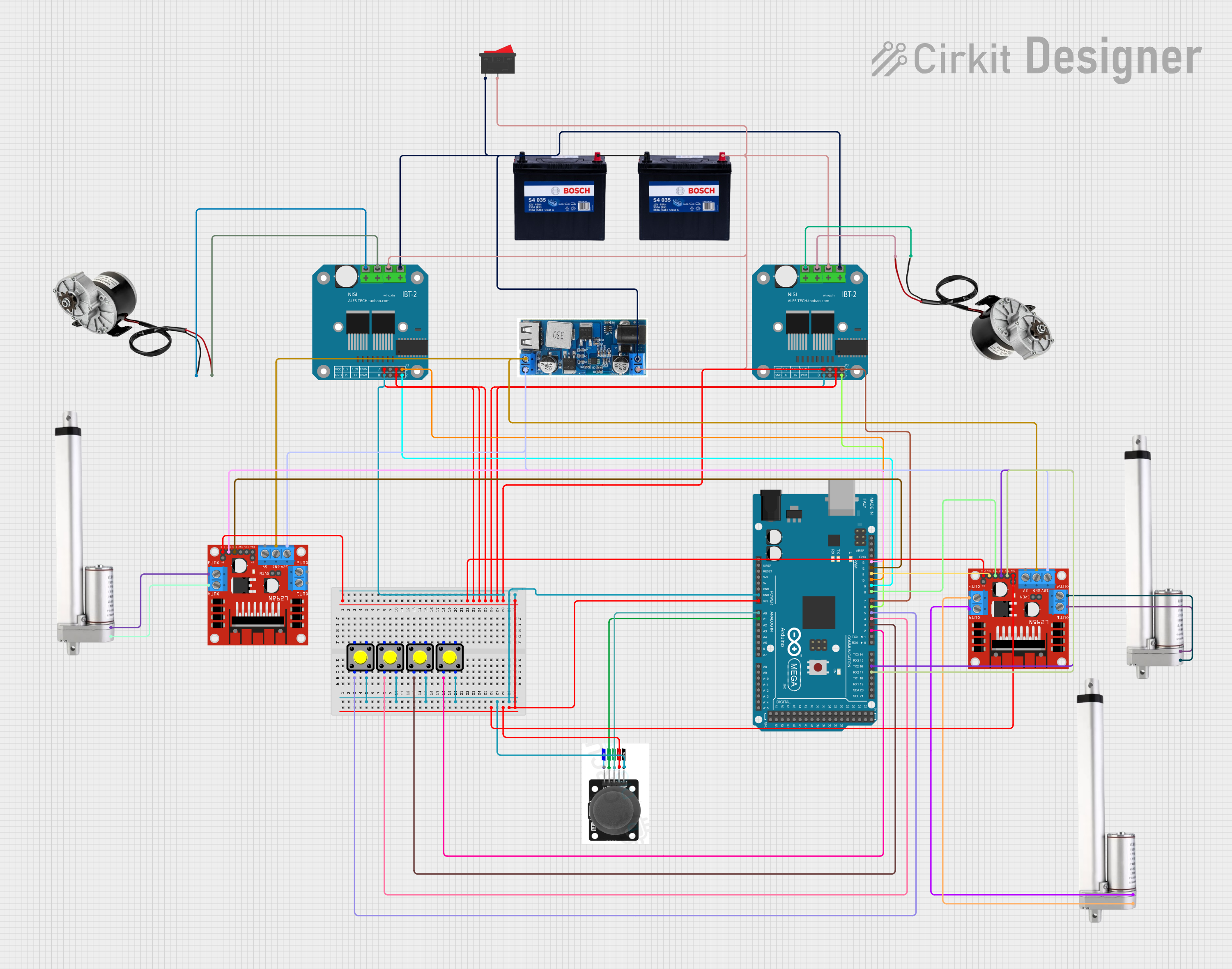
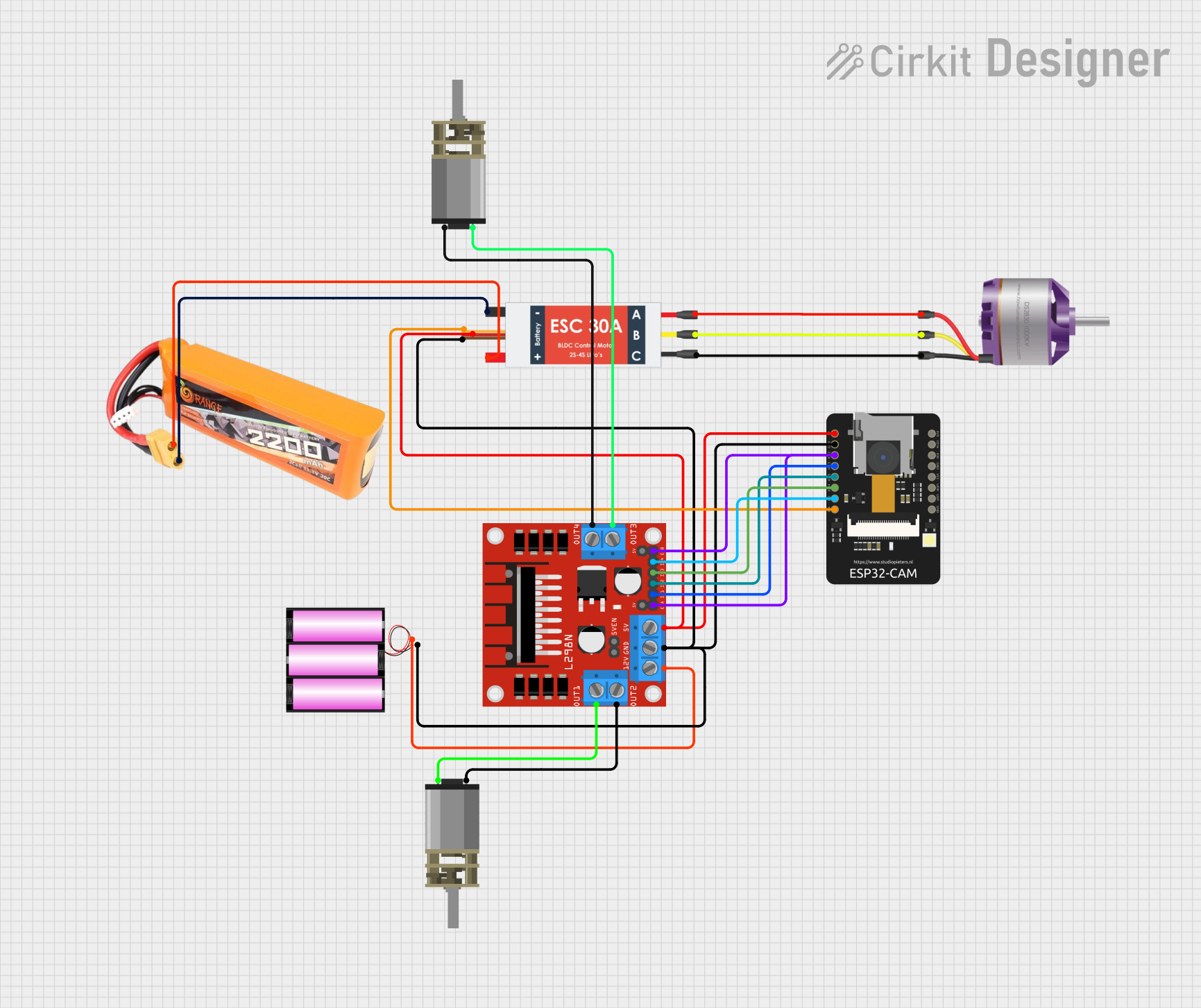
Explore Projects Built with (Arm) Driver Brushed Motor Controller
Common Applications and Use Cases
- Robotic arms
- Wheeled robots
- Actuators for automation systems
- Educational projects involving motor control
Technical Specifications
Key Technical Details
- Operating Voltage: 6V to 28V
- Continuous Current: Up to 12A
- Peak Current: 30A for a few seconds
- Control Signal Input: PWM (Pulse Width Modulation)
- Control Signal Voltage: 3.3V to 5V logic levels
- Dimensions: 50mm x 30mm x 20mm
- Weight: 35g
Pin Configuration and Descriptions
| Pin Number | Pin Name | Description |
|---|---|---|
| 1 | V+ | Motor power supply positive (6V to 28V) |
| 2 | GND | Ground connection for power and logic |
| 3 | OUTA | Output A to motor |
| 4 | OUTB | Output B to motor |
| 5 | PWM | PWM signal input for speed control |
| 6 | DIR | Direction control input (High/Low) |
| 7 | EN | Enable input (High to enable, Low to disable) |
| 8 | CS | Current sensing output (analog voltage) |
Usage Instructions
How to Use the Component in a Circuit
Power Connections:
- Connect the motor's power supply positive to the V+ pin.
- Connect the motor's power supply ground to the GND pin.
Motor Connections:
- Connect one terminal of the brushed motor to the OUTA pin.
- Connect the other terminal of the motor to the OUTB pin.
Control Signal Connections:
- Connect the PWM signal from the microcontroller to the PWM pin for speed control.
- Connect the direction control signal from the microcontroller to the DIR pin.
- Connect the enable signal from the microcontroller to the EN pin.
Current Sensing (Optional):
- Connect the CS pin to an analog input on the microcontroller to monitor motor current.
Important Considerations and Best Practices
- Ensure the power supply voltage and current ratings do not exceed the controller's specifications.
- Use a flyback diode across the motor terminals to protect against voltage spikes.
- Implement proper heat dissipation techniques if operating the motor controller near its maximum ratings.
- Always disable the motor controller (using the EN pin) before making or breaking connections to prevent damage.
Example Code for Arduino UNO
// Define motor control pins
#define PWM_PIN 3
#define DIR_PIN 4
#define EN_PIN 5

void setup() {
  // Set motor control pins as outputs
  pinMode(PWM_PIN, OUTPUT);
  pinMode(DIR_PIN, OUTPUT);
  pinMode(EN_PIN, OUTPUT);

  // Enable the motor controller
  digitalWrite(EN_PIN, HIGH);
}

void loop() {
  // Set motor direction
  digitalWrite(DIR_PIN, HIGH); // Set to LOW to reverse direction

  // Set motor speed (0 to 255)
  analogWrite(PWM_PIN, 128); // Adjust the value to control speed

  // Add your code to control the motor based on your application needs
}
Troubleshooting and FAQs
Common Issues
- Motor not responding: Check all connections, ensure the power supply is within specifications, and verify that the EN pin is set high to enable the controller.
- Overheating: If the controller is overheating, reduce the load or improve heat dissipation.
- Inconsistent motor speed: Ensure that the PWM signal is stable and within the correct voltage range.
Solutions and Tips for Troubleshooting
- Double-check wiring, especially the polarity of the motor and power supply connections.
- Use a multimeter to verify the presence of the control signals at the PWM and DIR pins.
- If current sensing is implemented, monitor the CS pin to ensure the motor is not drawing excessive current.
FAQs
Q: Can I control two motors with one controller? A: No, this controller is designed for a single motor. Use separate controllers for each motor.
Q: What is the maximum frequency for the PWM signal? A: The controller typically supports PWM frequencies up to 20kHz. Check the datasheet for exact specifications.
Q: How do I reverse the motor direction? A: Change the logic level of the DIR pin. High for one direction, Low for the opposite direction.
Q: Is it possible to use this controller with a 3.3V logic microcontroller? A: Yes, the controller accepts 3.3V to 5V logic levels for control signals.
For further assistance, consult the manufacturer's datasheet and technical support resources.