How to Use LM7805 blank board (Back): Examples, Pinouts, and Specs
Introduction
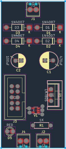
The LM7805 Blank Board (Back) is a printed circuit board (PCB) designed to house the LM7805 voltage regulator. This board simplifies the process of integrating the LM7805 into your circuit by providing a convenient layout for input and output connections, as well as space for supporting components such as capacitors. The LM7805 is a linear voltage regulator that outputs a stable 5V DC from a higher input voltage, making it ideal for powering microcontrollers, sensors, and other 5V devices.
Explore Projects Built with LM7805 blank board (Back)
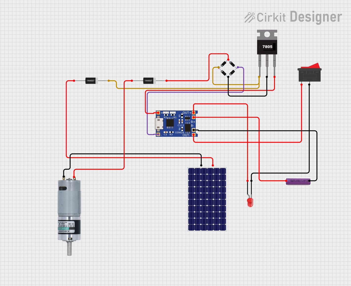


Explore Projects Built with LM7805 blank board (Back)
Common Applications and Use Cases
- Power supply for Arduino, Raspberry Pi, and other microcontrollers
- Voltage regulation for battery-powered devices
- Prototyping and DIY electronics projects
- Providing a stable 5V output for sensors, motors, and other components
Technical Specifications
The LM7805 Blank Board (Back) is designed to support the LM7805 voltage regulator and its associated components. Below are the key technical details:
Key Specifications
- Input Voltage Range: 7V to 35V DC (depending on the LM7805 regulator used)
- Output Voltage: 5V DC (regulated)
- Maximum Output Current: 1A (with proper heat dissipation for the LM7805)
- PCB Dimensions: Typically 25mm x 20mm (may vary slightly)
- Component Mounting: Through-hole for LM7805 and supporting components
- Material: FR4 PCB with solder mask and silkscreen
Pin Configuration and Descriptions
The LM7805 Blank Board (Back) provides labeled connections for the LM7805 regulator and supporting components. Below is the pin configuration:
| Pin Name | Description |
|---|---|
| IN | Input voltage pin. Connects to the positive terminal of the input power source. |
| GND | Ground pin. Connects to the negative terminal of the input power source. |
| OUT | Output voltage pin. Provides a regulated 5V DC output. |
Supporting Component Layout
The board includes space for the following components:
- Input Capacitor (C1): Typically 0.33µF to stabilize the input voltage.
- Output Capacitor (C2): Typically 0.1µF to stabilize the output voltage.
- Optional Heat Sink Mounting: Space for attaching a heat sink to the LM7805 for improved thermal performance.
Usage Instructions
How to Use the LM7805 Blank Board
- Solder the LM7805 Regulator: Place the LM7805 voltage regulator into the designated through-hole slots on the PCB. Ensure the pins are correctly aligned with the labels (IN, GND, OUT).
- Add Supporting Components: Solder the input capacitor (C1) and output capacitor (C2) in their respective positions. Use the recommended values (0.33µF for C1 and 0.1µF for C2) or refer to the LM7805 datasheet for specific requirements.
- Connect Input Power: Attach the input voltage source to the IN and GND pins. Ensure the input voltage is within the acceptable range (7V to 35V DC).
- Connect Output Load: Connect the device or circuit requiring 5V power to the OUT and GND pins.
- Optional Heat Sink: If the LM7805 is expected to dissipate significant heat (e.g., when drawing high current), attach a heat sink to the regulator.
Important Considerations and Best Practices
- Input Voltage: Ensure the input voltage is at least 2V higher than the desired 5V output (e.g., 7V minimum).
- Heat Dissipation: For currents above 500mA, consider using a heat sink to prevent the LM7805 from overheating.
- Capacitor Selection: Use high-quality capacitors with appropriate voltage ratings to ensure stable operation.
- Polarity: Double-check the polarity of all connections to avoid damaging the LM7805 or other components.
Example: Using the LM7805 Blank Board with Arduino UNO
Below is an example of how to use the LM7805 Blank Board to power an Arduino UNO:
Circuit Connections
- Connect a 9V battery to the IN and GND pins of the blank board.
- Connect the OUT and GND pins of the blank board to the Arduino UNO's 5V and GND pins, respectively.
Arduino Code Example
// Example code to blink an LED connected to pin 13 of the Arduino UNO
// Ensure the Arduino is powered via the LM7805 Blank Board

void setup() {
  pinMode(13, OUTPUT); // Set pin 13 as an output
}

void loop() {
  digitalWrite(13, HIGH); // Turn the LED on
  delay(1000);            // Wait for 1 second
  digitalWrite(13, LOW);  // Turn the LED off
  delay(1000);            // Wait for 1 second
}
Troubleshooting and FAQs
Common Issues and Solutions
No Output Voltage
- Cause: Incorrect input voltage or loose connections.
- Solution: Verify that the input voltage is within the acceptable range (7V to 35V) and check all connections.
Overheating
- Cause: Excessive current draw or insufficient heat dissipation.
- Solution: Attach a heat sink to the LM7805 and ensure the current draw does not exceed 1A.
Unstable Output Voltage
- Cause: Missing or incorrect capacitors.
- Solution: Ensure the input and output capacitors are properly installed and have the correct values.
Damaged LM7805
- Cause: Reverse polarity or excessive input voltage.
- Solution: Replace the LM7805 and double-check the polarity and input voltage before powering the circuit.
FAQs
Q: Can I use this board with a 12V input?
- A: Yes, the LM7805 can regulate a 12V input to 5V, provided the input voltage is at least 7V.
Q: Do I need a heat sink for low-current applications?
- A: No, a heat sink is typically unnecessary for currents below 500mA.
Q: Can I use this board to power a 3.3V device?
- A: No, the LM7805 outputs a fixed 5V. For 3.3V devices, consider using an LM7833 regulator or a buck converter.
Q: What is the maximum input voltage for this board?
- A: The LM7805 can handle up to 35V, but it is recommended to keep the input voltage below 25V for optimal performance and heat management.