How to Use INA219: Examples, Pinouts, and Specs
Introduction
The INA219 is a high-side current shunt monitor with an I2C interface, designed to measure both current and voltage with high precision. It is widely used in applications requiring accurate power consumption monitoring, such as battery management systems, energy monitoring, and industrial automation. By integrating a shunt resistor and leveraging its I2C communication capabilities, the INA219 simplifies the process of measuring power in embedded systems.
Explore Projects Built with INA219
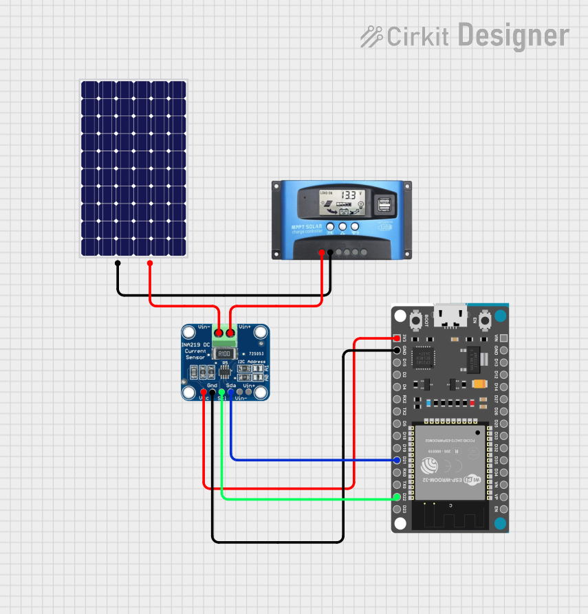
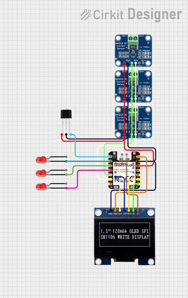
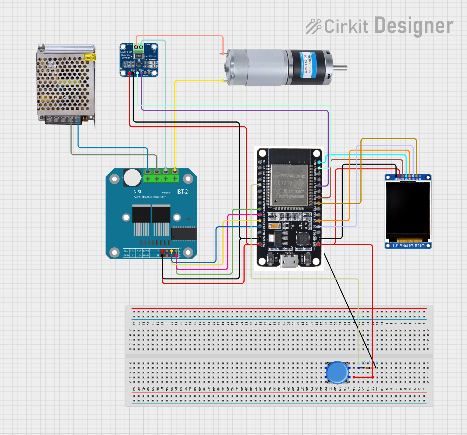
Explore Projects Built with INA219
Common Applications:
- Battery management systems
- Energy monitoring in IoT devices
- Solar power systems
- Industrial automation and control
- Robotics and motor control
Technical Specifications
The INA219 offers a range of features that make it versatile and reliable for power monitoring applications. Below are its key technical details:
Key Technical Details:
- Supply Voltage (Vcc): 3.0V to 5.5V
- Bus Voltage Range: 0V to 26V
- Current Measurement Range: ±3.2A (with default 0.1Ω shunt resistor)
- Resolution: 12-bit ADC
- Communication Protocol: I2C (up to 3.4 MHz)
- Default I2C Address: 0x40 (modifiable via address pins)
- Operating Temperature Range: -40°C to +125°C
- Power Consumption: 1 mA (typical)
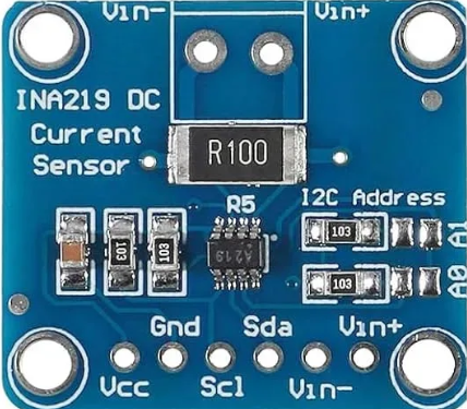
Pin Configuration and Descriptions:
The INA219 module typically comes with the following pins:
| Pin Name | Description |
|---|---|
| VCC | Power supply input (3.0V to 5.5V). |
| GND | Ground connection. |
| SCL | I2C clock line. Connect to the SCL pin of the microcontroller. |
| SDA | I2C data line. Connect to the SDA pin of the microcontroller. |
| VIN+ | Positive input for the shunt resistor (connect to the high side of the load). |
| VIN- | Negative input for the shunt resistor (connect to the low side of the load). |
| A0, A1 | Address pins for configuring the I2C address (optional, depending on the module). |
Usage Instructions
The INA219 is straightforward to use in a circuit, thanks to its I2C interface and integrated shunt resistor. Below are the steps and considerations for using the INA219 effectively:
Steps to Use the INA219:
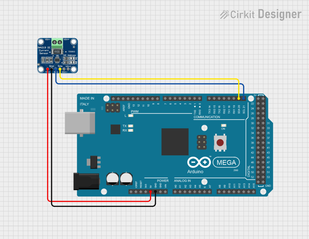
Connect the Power Supply:
- Connect the VCC pin to a 3.3V or 5V power source.
- Connect the GND pin to the ground of your circuit.
Connect the I2C Lines:
- Connect the SCL and SDA pins to the corresponding I2C pins on your microcontroller.
- Use pull-up resistors (typically 4.7kΩ) on the SCL and SDA lines if not already present.
Connect the Load:
- Connect the VIN+ pin to the positive side of the load.
- Connect the VIN- pin to the negative side of the load.
Configure the I2C Address (if needed):
- Use the A0 and A1 pins to set a custom I2C address if multiple INA219 modules are used.
Write Code to Read Data:
- Use an appropriate library (e.g., Adafruit INA219 library) to communicate with the INA219 and retrieve voltage, current, and power readings.
Example Code for Arduino UNO:
Below is an example of how to use the INA219 with an Arduino UNO:
#include <Wire.h>
#include <Adafruit_INA219.h>

// Create an instance of the INA219 class
Adafruit_INA219 ina219;

void setup() {
  Serial.begin(9600); // Initialize serial communication at 9600 baud
  while (!Serial) {
    delay(10); // Wait for the serial monitor to open
  }

  // Initialize the INA219 sensor
  if (!ina219.begin()) {
    Serial.println("Failed to find INA219 chip");
    while (1) {
      delay(10); // Halt execution if the sensor is not found
    }
  }
  Serial.println("INA219 initialized successfully");
}

void loop() {
  float shuntVoltage = ina219.getShuntVoltage_mV(); // Get shunt voltage in mV
  float busVoltage = ina219.getBusVoltage_V();      // Get bus voltage in V
  float current_mA = ina219.getCurrent_mA();        // Get current in mA
  float power_mW = ina219.getPower_mW();            // Get power in mW

  // Print the readings to the serial monitor
  Serial.print("Bus Voltage: ");
  Serial.print(busVoltage);
  Serial.println(" V");

  Serial.print("Shunt Voltage: ");
  Serial.print(shuntVoltage);
  Serial.println(" mV");

  Serial.print("Current: ");
  Serial.print(current_mA);
  Serial.println(" mA");

  Serial.print("Power: ");
  Serial.print(power_mW);
  Serial.println(" mW");

  Serial.println("-----------------------------");
  delay(1000); // Wait 1 second before the next reading
}
Important Considerations:
- Ensure the shunt resistor is appropriate for the expected current range. The default 0.1Ω resistor supports up to ±3.2A.
- Avoid exceeding the maximum bus voltage of 26V to prevent damage to the INA219.
- Use proper decoupling capacitors (e.g., 0.1µF) near the VCC pin for stable operation.
- If using multiple INA219 modules, configure unique I2C addresses using the A0 and A1 pins.
Troubleshooting and FAQs
Common Issues:
No Communication with the INA219:
- Cause: Incorrect I2C wiring or address mismatch.
- Solution: Verify the SCL and SDA connections and ensure the I2C address matches the code.
Incorrect Current or Voltage Readings:
- Cause: Improper shunt resistor value or loose connections.
- Solution: Check the shunt resistor and ensure all connections are secure.
INA219 Not Detected:
- Cause: Faulty module or incorrect power supply voltage.
- Solution: Ensure the module is powered correctly and test with another INA219.
FAQs:
Q: Can the INA219 measure negative currents?
A: Yes, the INA219 can measure bidirectional currents if configured appropriately.Q: What is the maximum sampling rate of the INA219?
A: The INA219 supports a maximum sampling rate of approximately 12-bit resolution at 532µs per conversion.Q: Can I use the INA219 with a 3.3V microcontroller?
A: Yes, the INA219 is compatible with both 3.3V and 5V logic levels.
By following this documentation, you can effectively integrate the INA219 into your projects for precise power monitoring and management.