Cirkit Designer Logo
Cirkit Designer
Your all-in-one circuit design IDE
Home / 
Component Documentation

How to Use Arcade Button (green): Examples, Pinouts, and Specs

Image of Arcade Button (green)
Cirkit Designer LogoDesign with Arcade Button (green) in Cirkit Designer

Introduction

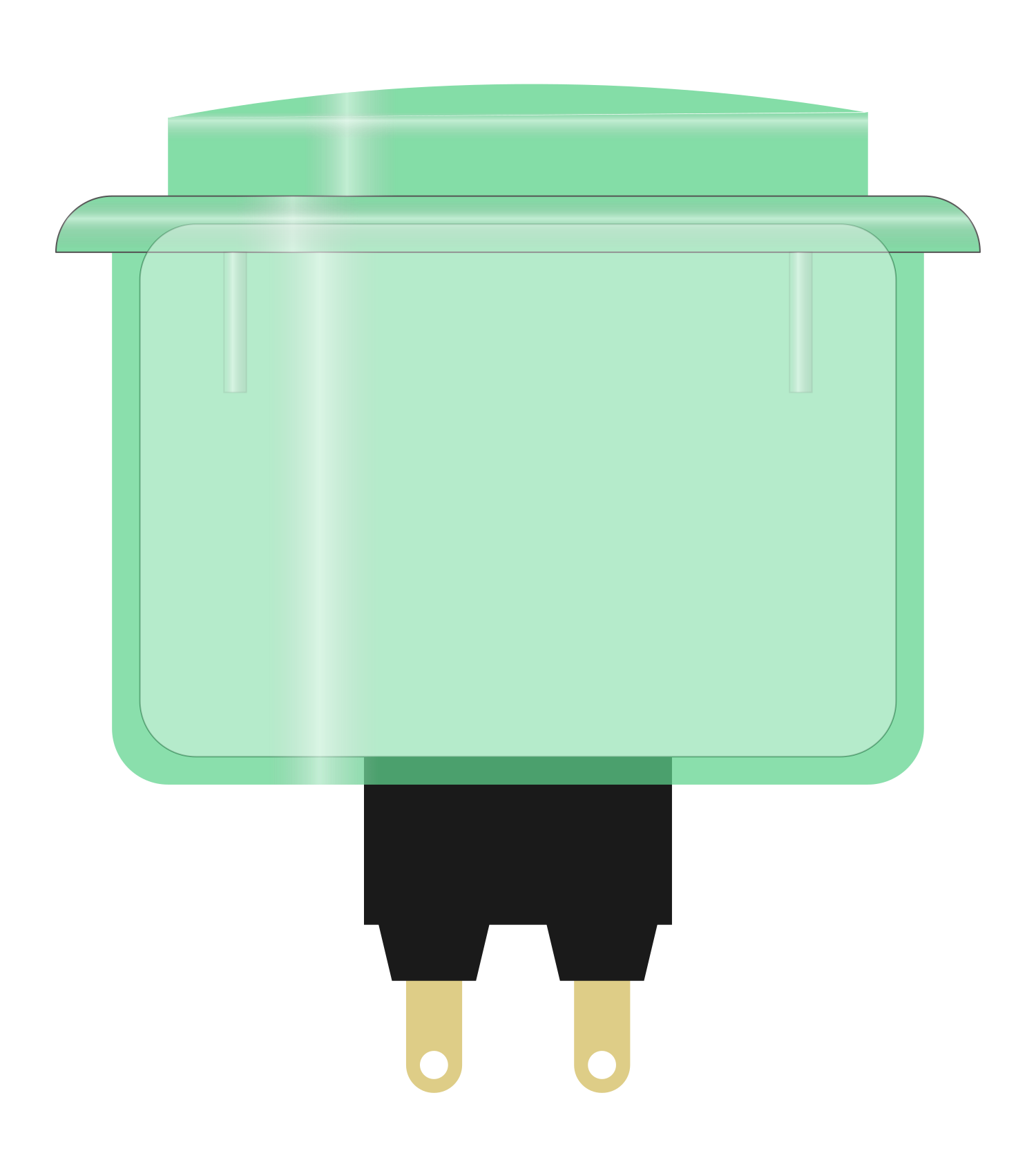
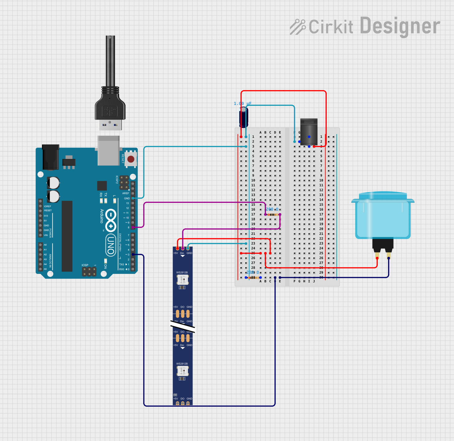
The Arcade Button (Green) is a robust and tactile push button switch designed for high-use environments such as arcade gaming cabinets. Its large actuator surface provides an easy-to-press interface, making it ideal for interactive projects that require user input. The button's vibrant green color adds a visual appeal and can be used to signify specific actions in applications.

Explore Projects Built with Arcade Button (green)

Use Cirkit Designer to design, explore, and prototype these projects online. Some projects support real-time simulation. Click "Open Project" to start designing instantly!
Arduino 101 LED Control with Push Button
Image of led on off ckt4: A project utilizing Arcade Button (green) in a practical application
This circuit uses an Arduino 101 to control a green LED via a push button. When the button is pressed, the Arduino reads the input and turns on the LED; when the button is released, the LED turns off.
Cirkit Designer LogoOpen Project in Cirkit Designer
Arduino Nano Battery-Powered RF Transmitter with Arcade Button
Image of remoterf: A project utilizing Arcade Button (green) in a practical application
This circuit consists of an Arduino Nano microcontroller connected to an RF transmitter module and a green arcade button. The Arduino Nano is powered by a 18650 Li-ion battery and controls the RF module to transmit data when the arcade button is pressed.
Cirkit Designer LogoOpen Project in Cirkit Designer
Arduino Mega 2560-Based Interactive Game with RGB LEDs, LCD Display, and DFPlayer Audio
Image of Game: A project utilizing Arcade Button (green) in a practical application
This circuit is a game controller that uses an Arduino Mega 2560 to manage inputs from multiple arcade buttons, control RGB LEDs, display messages on an LCD, and play audio through a DFPlayer module. The system announces the winner based on button presses, lights up the corresponding RGB LED, and displays the winner's name on the LCD.
Cirkit Designer LogoOpen Project in Cirkit Designer
Arduino UNO Controlled RGB LED Strip with Interactive Button
Image of Simon Circuit: A project utilizing Arcade Button (green) in a practical application
This circuit features an Arduino UNO connected to a WS2812 RGB LED strip, controlled via digital pin D8. An arcade button is interfaced with the Arduino through a resistor and digital pin D3, likely for user input to control the LED strip. Power is supplied through a 2.1mm DC barrel jack, with an electrolytic capacitor for voltage smoothing, and the ground connections are shared among the components.
Cirkit Designer LogoOpen Project in Cirkit Designer

Explore Projects Built with Arcade Button (green)

Use Cirkit Designer to design, explore, and prototype these projects online. Some projects support real-time simulation. Click "Open Project" to start designing instantly!
Image of led on off ckt4: A project utilizing Arcade Button (green) in a practical application
Arduino 101 LED Control with Push Button
This circuit uses an Arduino 101 to control a green LED via a push button. When the button is pressed, the Arduino reads the input and turns on the LED; when the button is released, the LED turns off.
Cirkit Designer LogoOpen Project in Cirkit Designer
Image of remoterf: A project utilizing Arcade Button (green) in a practical application
Arduino Nano Battery-Powered RF Transmitter with Arcade Button
This circuit consists of an Arduino Nano microcontroller connected to an RF transmitter module and a green arcade button. The Arduino Nano is powered by a 18650 Li-ion battery and controls the RF module to transmit data when the arcade button is pressed.
Cirkit Designer LogoOpen Project in Cirkit Designer
Image of Game: A project utilizing Arcade Button (green) in a practical application
Arduino Mega 2560-Based Interactive Game with RGB LEDs, LCD Display, and DFPlayer Audio
This circuit is a game controller that uses an Arduino Mega 2560 to manage inputs from multiple arcade buttons, control RGB LEDs, display messages on an LCD, and play audio through a DFPlayer module. The system announces the winner based on button presses, lights up the corresponding RGB LED, and displays the winner's name on the LCD.
Cirkit Designer LogoOpen Project in Cirkit Designer
Image of Simon Circuit: A project utilizing Arcade Button (green) in a practical application
Arduino UNO Controlled RGB LED Strip with Interactive Button
This circuit features an Arduino UNO connected to a WS2812 RGB LED strip, controlled via digital pin D8. An arcade button is interfaced with the Arduino through a resistor and digital pin D3, likely for user input to control the LED strip. Power is supplied through a 2.1mm DC barrel jack, with an electrolytic capacitor for voltage smoothing, and the ground connections are shared among the components.
Cirkit Designer LogoOpen Project in Cirkit Designer

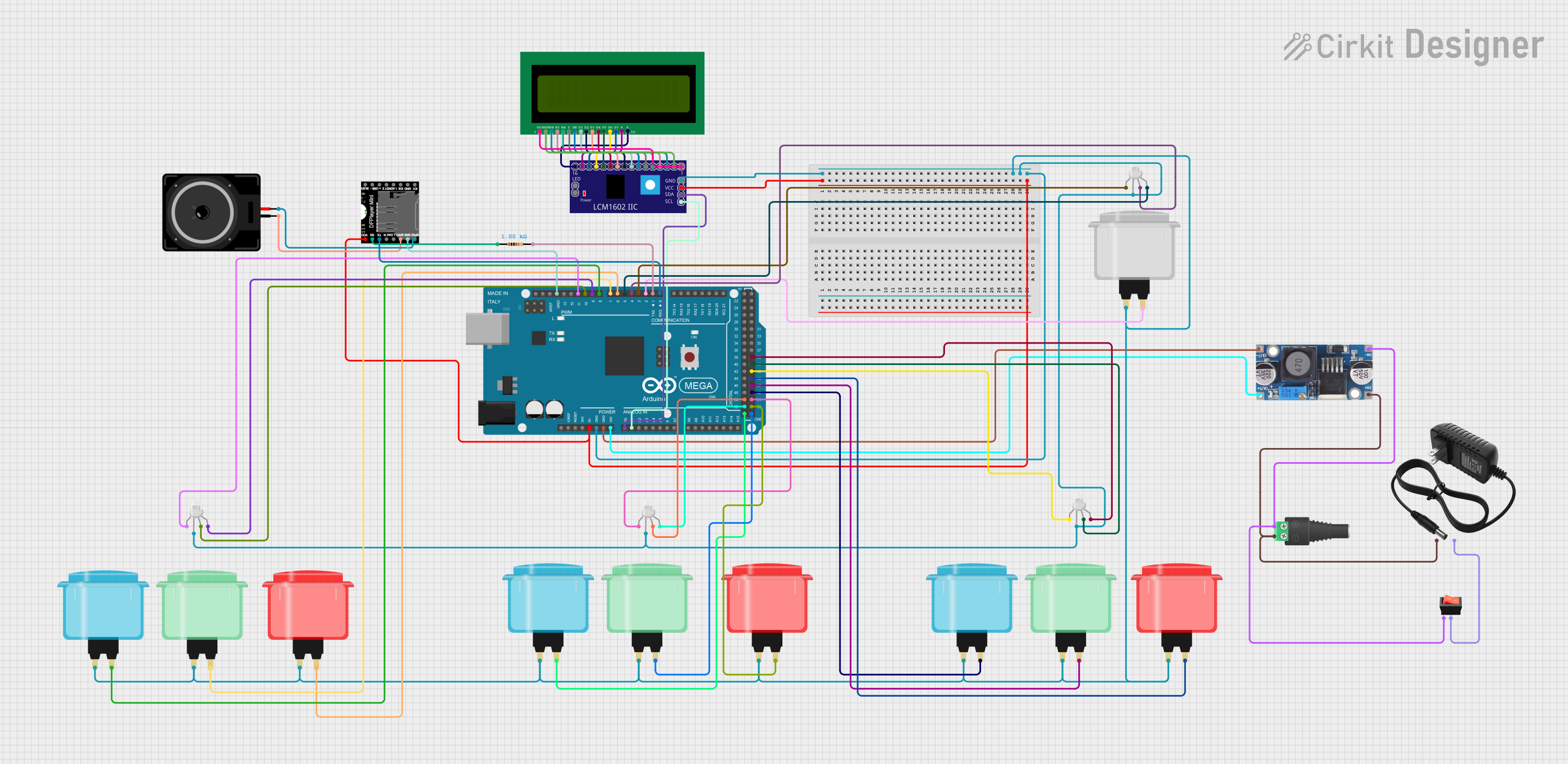
Common Applications and Use Cases

  • Arcade game machines
  • DIY game controllers
  • Interactive art installations
  • Educational projects
  • Home automation interfaces

Technical Specifications

Key Technical Details

  • Switch Type: Momentary push button
  • Color: Green
  • Material: Durable plastic (actuator) and metal (base)
  • Contact Rating: Typically 5A at 250VAC
  • Bounce Time: <10ms
  • Mounting Hole Diameter: 28mm to 30mm
  • Button Diameter: Approximately 40mm
  • Terminal Type: Microswitch with .187" (4.75mm) spade connectors

Pin Configuration and Descriptions

Pin Number Description Notes
1 Normally Open (NO) Connects to signal when pressed
2 Common (COM) Connects to ground
3 Normally Closed (NC) Connected to signal by default

Usage Instructions

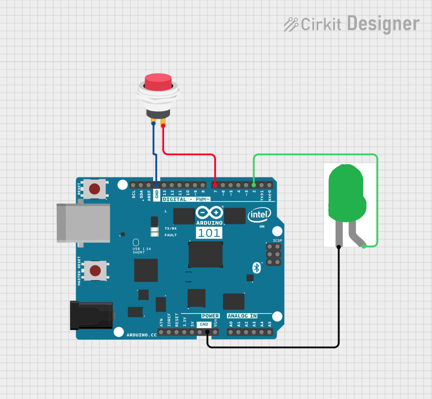
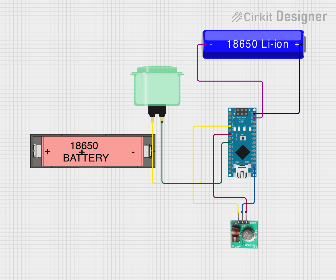
How to Use the Component in a Circuit

  1. Mounting the Button: Secure the button into a panel with a hole diameter between 28mm and 30mm. Ensure it is firmly in place.
  2. Wiring the Button: Connect the COM pin to the ground of your circuit. The NO pin should be connected to the input pin on your microcontroller or interface circuit. The NC pin is not used unless you require a normally closed configuration.
  3. Debouncing: Although the button has a low bounce time, it is recommended to implement a debounce algorithm in your code to ensure reliable state changes.

Important Considerations and Best Practices

  • Voltage and Current Ratings: Do not exceed the voltage and current ratings of the button to avoid damage.
  • Wiring: Ensure secure connections to the microswitch terminals. Loose connections can result in intermittent behavior.
  • Mounting: When mounting the button, make sure there is enough space behind the panel to accommodate the switch mechanism.

Example Code for Arduino UNO

// Define the pin where the arcade button is connected
const int buttonPin = 2;
// Variable to store the button state
bool buttonState = 0;

void setup() {
  // Initialize the button pin as an input
  pinMode(buttonPin, INPUT_PULLUP);
  // Begin serial communication at 9600 baud rate
  Serial.begin(9600);
}

void loop() {
  // Read the state of the button
  buttonState = digitalRead(buttonPin);
  // Check if the button is pressed
  if (buttonState == LOW) {
    // If the button is pressed, print a message
    Serial.println("Button Pressed!");
    // Add a small delay to debounce the button
    delay(50);
  }
}

Troubleshooting and FAQs

Common Issues

  • Button does not respond: Ensure the button is correctly wired and the connections are secure. Check if the microswitch is functioning properly.
  • Intermittent button presses: This could be due to loose connections or a need for debouncing in the code.
  • Button sticks when pressed: The button may be mounted too tightly. Loosen the mounting nut slightly.

Solutions and Tips for Troubleshooting

  • Check Connections: Verify that all connections are secure and that the correct terminals are used.
  • Test the Microswitch: Use a multimeter to test the continuity of the microswitch in both the pressed and released states.
  • Implement Debouncing: Ensure that your code accounts for switch bounce to prevent false triggering.

FAQs

Q: Can I use the Arcade Button with a 5V system? A: Yes, the Arcade Button can be used with a 5V system, such as an Arduino UNO.

Q: How do I know if the button is pressed in my code? A: When the button is pressed, the digital pin connected to the NO terminal will read LOW if you're using the INPUT_PULLUP configuration.

Q: Can I light up the Arcade Button? A: Some Arcade Buttons come with built-in LEDs. If yours has one, you can connect the LED terminals to a power source with the appropriate current-limiting resistor. If not, you will need to modify the button or use an external light source.

Q: Is it necessary to use the NC terminal? A: The NC terminal is not necessary for a simple push-to-make circuit. It is used in applications where a normally closed configuration is required.