Cirkit Designer Logo
Cirkit Designer
Your all-in-one circuit design IDE
Home / 
Component Documentation

How to Use ESP32 Dev Module: Examples, Pinouts, and Specs

Image of ESP32 Dev Module
Cirkit Designer LogoDesign with ESP32 Dev Module in Cirkit Designer

Introduction

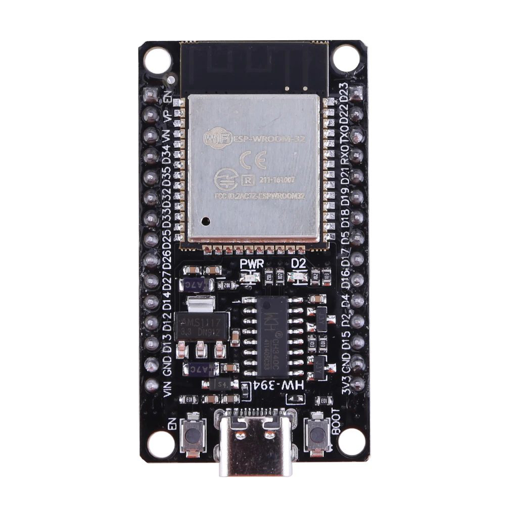
The ESP32 Dev Module, manufactured by Espressif Systems (Part ID: ESP32-WROOM-32), is a powerful and versatile microcontroller module designed for a wide range of applications. It features integrated Wi-Fi and Bluetooth capabilities, making it an excellent choice for Internet of Things (IoT) projects, smart devices, and rapid prototyping.

With its dual-core processor, extensive GPIO options, and support for various communication protocols, the ESP32 Dev Module is suitable for both beginners and experienced developers. Its compact size and low power consumption further enhance its usability in embedded systems.

Explore Projects Built with ESP32 Dev Module

Use Cirkit Designer to design, explore, and prototype these projects online. Some projects support real-time simulation. Click "Open Project" to start designing instantly!
ESP32-Based GPS Tracker with SD Card Logging and Barometric Sensor
Image of gps projekt circuit: A project utilizing ESP32 Dev Module in a practical application
This circuit features an ESP32 Wroom Dev Kit as the main microcontroller, interfaced with an MPL3115A2 sensor for pressure and temperature readings, and a Neo 6M GPS module for location tracking. The ESP32 is also connected to an SD card reader for data logging purposes. A voltage regulator is used to step down the USB power supply to 3.3V, which powers the ESP32, the sensor, and the SD card reader.
Cirkit Designer LogoOpen Project in Cirkit Designer
ESP32-Based Environmental Monitoring and Alert System with Solar Charging
Image of mark: A project utilizing ESP32 Dev Module in a practical application
This circuit features an ESP32 Devkit V1 microcontroller connected to various sensors and modules for monitoring and communication purposes. It includes an MQ-2 gas sensor and a DHT11 temperature and humidity sensor, both interfaced with the ESP32 for environmental data collection. The circuit is powered by a 12V battery, regulated to 5V by step-down converters, and includes a solar charge controller connected to a solar panel for battery charging, a UPS module for power management, and a SIM900A module for GSM communication. Additionally, there is a WS2812 RGB LED strip for visual feedback and a piezo buzzer for audio alerts, both controlled by the ESP32.
Cirkit Designer LogoOpen Project in Cirkit Designer
ESP32-Based Smart Agriculture System with LoRa Communication
Image of Soil Monitoring Device: A project utilizing ESP32 Dev Module in a practical application
This circuit features an ESP32 Devkit V1 microcontroller as the central processing unit, interfacing with various sensors including a PH Meter, an NPK Soil Sensor, and a Soil Moisture Sensor for environmental data collection. It also includes an EBYTE LoRa E220 module for wireless communication. Power management is handled by a Step Up Boost Power Converter, which is connected to a 12V Battery, stepping up the voltage to power the ESP32 and sensors, with common ground connections throughout the circuit.
Cirkit Designer LogoOpen Project in Cirkit Designer
ESP32-Based Environmental Monitoring and Alert System with Solar Charging
Image of Schematic: A project utilizing ESP32 Dev Module in a practical application
This circuit features an ESP32 Devkit V1 microcontroller connected to various sensors and devices, including a DHT11 temperature and humidity sensor, an MQ-2 gas sensor, and a WS2812 RGB LED strip. The ESP32 controls the LED strip and processes sensor readings, while a SIM900A module provides cellular communication capabilities. Power management is handled by a UPS module fed by a 12V battery charged via a solar panel and charge controller, with voltage regulation provided by step-down converters. Additionally, a piezo buzzer is included for audible alerts, and the system's safety is ensured by a circuit breaker connected to a switching power supply for AC to DC conversion.
Cirkit Designer LogoOpen Project in Cirkit Designer

Explore Projects Built with ESP32 Dev Module

Use Cirkit Designer to design, explore, and prototype these projects online. Some projects support real-time simulation. Click "Open Project" to start designing instantly!
Image of gps projekt circuit: A project utilizing ESP32 Dev Module in a practical application
ESP32-Based GPS Tracker with SD Card Logging and Barometric Sensor
This circuit features an ESP32 Wroom Dev Kit as the main microcontroller, interfaced with an MPL3115A2 sensor for pressure and temperature readings, and a Neo 6M GPS module for location tracking. The ESP32 is also connected to an SD card reader for data logging purposes. A voltage regulator is used to step down the USB power supply to 3.3V, which powers the ESP32, the sensor, and the SD card reader.
Cirkit Designer LogoOpen Project in Cirkit Designer
Image of mark: A project utilizing ESP32 Dev Module in a practical application
ESP32-Based Environmental Monitoring and Alert System with Solar Charging
This circuit features an ESP32 Devkit V1 microcontroller connected to various sensors and modules for monitoring and communication purposes. It includes an MQ-2 gas sensor and a DHT11 temperature and humidity sensor, both interfaced with the ESP32 for environmental data collection. The circuit is powered by a 12V battery, regulated to 5V by step-down converters, and includes a solar charge controller connected to a solar panel for battery charging, a UPS module for power management, and a SIM900A module for GSM communication. Additionally, there is a WS2812 RGB LED strip for visual feedback and a piezo buzzer for audio alerts, both controlled by the ESP32.
Cirkit Designer LogoOpen Project in Cirkit Designer
Image of Soil Monitoring Device: A project utilizing ESP32 Dev Module in a practical application
ESP32-Based Smart Agriculture System with LoRa Communication
This circuit features an ESP32 Devkit V1 microcontroller as the central processing unit, interfacing with various sensors including a PH Meter, an NPK Soil Sensor, and a Soil Moisture Sensor for environmental data collection. It also includes an EBYTE LoRa E220 module for wireless communication. Power management is handled by a Step Up Boost Power Converter, which is connected to a 12V Battery, stepping up the voltage to power the ESP32 and sensors, with common ground connections throughout the circuit.
Cirkit Designer LogoOpen Project in Cirkit Designer
Image of Schematic: A project utilizing ESP32 Dev Module in a practical application
ESP32-Based Environmental Monitoring and Alert System with Solar Charging
This circuit features an ESP32 Devkit V1 microcontroller connected to various sensors and devices, including a DHT11 temperature and humidity sensor, an MQ-2 gas sensor, and a WS2812 RGB LED strip. The ESP32 controls the LED strip and processes sensor readings, while a SIM900A module provides cellular communication capabilities. Power management is handled by a UPS module fed by a 12V battery charged via a solar panel and charge controller, with voltage regulation provided by step-down converters. Additionally, a piezo buzzer is included for audible alerts, and the system's safety is ensured by a circuit breaker connected to a switching power supply for AC to DC conversion.
Cirkit Designer LogoOpen Project in Cirkit Designer

Common Applications and Use Cases

  • IoT devices and smart home automation
  • Wireless sensor networks
  • Wearable technology
  • Robotics and drones
  • Industrial automation
  • Prototyping and educational projects

Technical Specifications

Key Technical Details

Parameter Value
Microcontroller Tensilica Xtensa LX6 dual-core processor
Clock Speed Up to 240 MHz
Flash Memory 4 MB (default, expandable depending on the module variant)
SRAM 520 KB
Wireless Connectivity Wi-Fi 802.11 b/g/n, Bluetooth v4.2 + BLE
Operating Voltage 3.3V
Input Voltage Range 5V (via USB) or 3.3V (via VIN pin)
GPIO Pins 34 (multipurpose, including ADC, DAC, PWM, I2C, SPI, UART, etc.)
ADC Resolution 12-bit
DAC Resolution 8-bit
Power Consumption Ultra-low power consumption in deep sleep mode (~10 µA)
Operating Temperature -40°C to +85°C
Dimensions 25.5 mm x 18 mm x 3 mm

Pin Configuration and Descriptions

The ESP32 Dev Module has a total of 38 pins. Below is a summary of the key pins and their functions:

Pin Name Type Description
VIN Power Input Input voltage (5V) for powering the module via an external source.
GND Ground Ground connection.
3V3 Power Output Regulated 3.3V output from the onboard voltage regulator.
EN Enable Active-high pin to enable or reset the module.
GPIO0 GPIO General-purpose I/O pin; also used for boot mode selection.
GPIO2 GPIO General-purpose I/O pin; supports PWM, ADC, and other functions.
GPIO12-15 GPIO Multipurpose pins; can be used for SPI, I2C, UART, or other peripherals.
TXD0, RXD0 UART Default UART0 pins for serial communication.
ADC1_CH0-7 ADC Input 12-bit ADC channels for analog input.
DAC1, DAC2 DAC Output 8-bit DAC channels for analog output.
IO34-39 Input Only GPIO pins that can only be used as inputs.
BOOT Boot Mode Used to enter bootloader mode for flashing firmware.

Usage Instructions

How to Use the ESP32 Dev Module in a Circuit

  1. Powering the Module:

    • Connect the VIN pin to a 5V power source or use the onboard USB connector.
    • Ensure the GND pin is connected to the ground of your circuit.
    • The onboard voltage regulator will provide 3.3V to the ESP32.
  2. Programming the Module:

    • Use a USB cable to connect the ESP32 Dev Module to your computer.
    • Install the necessary drivers (e.g., CP210x or CH340, depending on the module variant).
    • Use the Arduino IDE or Espressif's ESP-IDF framework to write and upload code.
  3. Connecting Peripherals:

    • Use the GPIO pins for connecting sensors, actuators, and other peripherals.
    • Refer to the pin configuration table to ensure proper pin usage.
  4. Wi-Fi and Bluetooth Setup:

    • Use the built-in libraries (e.g., WiFi.h and BluetoothSerial.h in Arduino IDE) to configure wireless communication.

Important Considerations and Best Practices

  • Voltage Levels: Ensure all connected peripherals operate at 3.3V logic levels to avoid damaging the module.
  • Boot Mode: To enter bootloader mode, hold the BOOT button while pressing the EN button.
  • Power Supply: Use a stable power source to avoid unexpected resets or malfunctions.
  • Deep Sleep Mode: Utilize the deep sleep mode for battery-powered applications to minimize power consumption.

Example Code for Arduino UNO Integration

Below is an example of how to connect the ESP32 Dev Module to a Wi-Fi network using the Arduino IDE:

#include <WiFi.h> // Include the WiFi library for ESP32

const char* ssid = "Your_SSID";       // Replace with your Wi-Fi network name
const char* password = "Your_Password"; // Replace with your Wi-Fi password

void setup() {
  Serial.begin(115200); // Initialize serial communication at 115200 baud
  delay(1000);          // Wait for a moment to stabilize

  Serial.println("Connecting to Wi-Fi...");
  WiFi.begin(ssid, password); // Start Wi-Fi connection

  while (WiFi.status() != WL_CONNECTED) {
    delay(500); // Wait until the connection is established
    Serial.print(".");
  }

  Serial.println("\nWi-Fi connected!");
  Serial.print("IP Address: ");
  Serial.println(WiFi.localIP()); // Print the assigned IP address
}

void loop() {
  // Add your main code here
}

Troubleshooting and FAQs

Common Issues and Solutions

  1. ESP32 Not Detected by Computer:

    • Ensure the correct USB drivers (CP210x or CH340) are installed.
    • Try a different USB cable or port.
  2. Wi-Fi Connection Fails:

    • Double-check the SSID and password.
    • Ensure the Wi-Fi network is within range and not using unsupported security protocols.
  3. Module Keeps Resetting:

    • Verify the power supply is stable and capable of providing sufficient current (at least 500 mA).
    • Check for short circuits or incorrect wiring.
  4. Code Upload Fails:

    • Ensure the correct board and port are selected in the Arduino IDE.
    • Hold the BOOT button while uploading the code to enter bootloader mode.

FAQs

  • Q: Can the ESP32 Dev Module operate on battery power?
    A: Yes, the module can be powered using a 3.7V LiPo battery connected to the VIN pin, but ensure proper voltage regulation.

  • Q: How do I reset the ESP32?
    A: Press the EN button to reset the module.

  • Q: Can I use the ESP32 with other IDEs besides Arduino?
    A: Yes, the ESP32 is compatible with Espressif's ESP-IDF, PlatformIO, and other development environments.