How to Use ESP12F_Relay: Examples, Pinouts, and Specs
Introduction
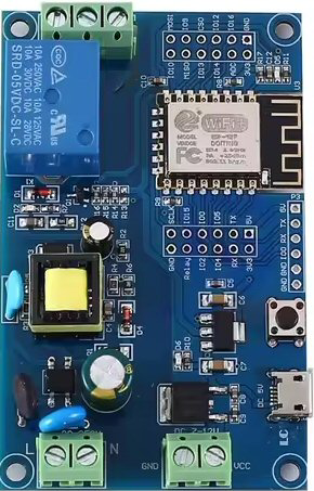
The ESP12F Relay (Manufacturer Part ID: ESP12F_Relay_X1_V1.2) is a Wi-Fi-enabled relay module designed and manufactured by Laroal. This module integrates the ESP8266 microcontroller, which provides wireless communication capabilities, making it ideal for IoT (Internet of Things) applications. The relay allows users to remotely control electrical devices, such as lights, fans, or appliances, through a Wi-Fi connection.
Explore Projects Built with ESP12F_Relay


Explore Projects Built with ESP12F_Relay
Common Applications and Use Cases
- Home Automation: Control lights, fans, or other appliances remotely.
- Industrial Automation: Manage machinery or equipment wirelessly.
- IoT Projects: Integrate with smart home systems or cloud platforms.
- Prototyping: Develop and test wireless control systems for various devices.
Technical Specifications
The following table outlines the key technical details of the ESP12F Relay module:
| Parameter | Specification |
|---|---|
| Operating Voltage | 5V DC |
| Relay Control Voltage | 3.3V (logic level from ESP8266) |
| Relay Output Voltage | 250V AC / 30V DC (max) |
| Relay Output Current | 10A (max) |
| Wi-Fi Standard | IEEE 802.11 b/g/n (2.4 GHz) |
| Microcontroller | ESP8266 (ESP-12F module) |
| Communication Protocol | Wi-Fi (TCP/IP, HTTP, MQTT, etc.) |
| Dimensions | 50mm x 25mm x 18mm |
Pin Configuration and Descriptions
The ESP12F Relay module has the following pinout:
| Pin Name | Description |
|---|---|
| VCC | Power input (5V DC). Supplies power to the module. |
| GND | Ground connection. |
| IN | Relay control pin. A HIGH signal activates the relay, and a LOW signal deactivates it. |
| TX | UART Transmit pin for serial communication. |
| RX | UART Receive pin for serial communication. |
| GPIO0 | General-purpose I/O pin. Can be used for custom configurations. |
| GPIO2 | General-purpose I/O pin. Can be used for custom configurations. |
| GPIO15 | General-purpose I/O pin. Can be used for custom configurations. |
Usage Instructions
How to Use the ESP12F Relay in a Circuit
- Power the Module: Connect the VCC pin to a 5V DC power source and the GND pin to ground.
- Control the Relay: Use the IN pin to control the relay. A HIGH signal (3.3V) activates the relay, while a LOW signal (0V) deactivates it.
- Connect the Load: Wire the electrical device (e.g., light or fan) to the relay's output terminals. Ensure the load does not exceed the relay's maximum ratings (250V AC, 10A).
- Program the ESP8266: Use the TX and RX pins to upload firmware or communicate with the ESP8266. You can program it using the Arduino IDE or other compatible tools.
Important Considerations and Best Practices
- Power Supply: Ensure a stable 5V DC power supply to avoid malfunctions.
- Isolation: The relay provides electrical isolation between the control circuit and the load. However, take precautions when working with high voltages.
- Wi-Fi Configuration: Configure the ESP8266 for your Wi-Fi network using appropriate firmware or code.
- Load Ratings: Do not exceed the relay's maximum voltage and current ratings to prevent damage.
Example Code for Arduino UNO
Below is an example of how to control the ESP12F Relay using an Arduino UNO:
// Include the SoftwareSerial library for communication with ESP8266
#include <SoftwareSerial.h>

// Define pins for SoftwareSerial
SoftwareSerial espSerial(2, 3); // RX, TX

// Define the relay control pin
#define RELAY_PIN 4

void setup() {
  // Initialize serial communication
  Serial.begin(9600); // For debugging
  espSerial.begin(9600); // For ESP8266 communication

  // Set the relay pin as output
  pinMode(RELAY_PIN, OUTPUT);

  // Turn off the relay initially
  digitalWrite(RELAY_PIN, LOW);

  Serial.println("ESP12F Relay Example Initialized");
}

void loop() {
  // Example: Turn the relay ON for 5 seconds, then OFF for 5 seconds
  Serial.println("Turning Relay ON");
  digitalWrite(RELAY_PIN, HIGH); // Activate the relay
  delay(5000); // Wait for 5 seconds

  Serial.println("Turning Relay OFF");
  digitalWrite(RELAY_PIN, LOW); // Deactivate the relay
  delay(5000); // Wait for 5 seconds
}
Notes:
- Connect the Arduino's digital pin 4 to the IN pin of the ESP12F Relay.
- Ensure the ESP12F Relay is powered with 5V DC and properly grounded.
Troubleshooting and FAQs
Common Issues and Solutions
Relay Not Activating
- Cause: Insufficient voltage or incorrect wiring.
- Solution: Verify that the VCC pin is receiving 5V DC and the IN pin is connected to a 3.3V logic signal.
Wi-Fi Connection Fails
- Cause: Incorrect Wi-Fi credentials or poor signal strength.
- Solution: Double-check the SSID and password in your ESP8266 firmware. Ensure the module is within range of the Wi-Fi router.
Load Not Switching
- Cause: Load exceeds the relay's maximum ratings or incorrect wiring.
- Solution: Ensure the load is within the relay's voltage and current limits. Verify the wiring of the load to the relay's output terminals.
ESP8266 Not Responding
- Cause: Incorrect baud rate or wiring of TX/RX pins.
- Solution: Ensure the baud rate in your code matches the ESP8266's default baud rate (usually 9600 or 115200). Check the TX and RX connections.
FAQs
Can I use a 3.3V power supply for the ESP12F Relay?
- No, the module requires a 5V DC power supply for proper operation.
Is the relay safe for high-power devices?
- Yes, as long as the device's voltage and current ratings do not exceed 250V AC and 10A.
Can I control the relay using a smartphone?
- Yes, you can configure the ESP8266 to communicate with a smartphone app via Wi-Fi.
What programming tools are compatible with the ESP8266?
- The ESP8266 can be programmed using the Arduino IDE, NodeMCU firmware, or other compatible tools.
By following this documentation, you can effectively integrate the ESP12F Relay into your projects and troubleshoot common issues.