How to Use h3lis331DL accelerometer breakout: Examples, Pinouts, and Specs
Introduction
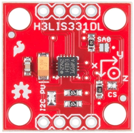
The H3LIS331DL accelerometer breakout, manufactured by SparkFun (Part ID: SEN-14480), is a compact and versatile sensor module designed to measure acceleration in three axes: X, Y, and Z. It features high sensitivity, low power consumption, and a wide measurement range, making it suitable for a variety of applications. This breakout board is ideal for motion detection, orientation sensing, and vibration monitoring in robotics, mobile devices, and wearable technology.
Explore Projects Built with h3lis331DL accelerometer breakout

Explore Projects Built with h3lis331DL accelerometer breakout
Common Applications
- Motion detection in robotics and drones
- Orientation sensing in mobile devices
- Vibration monitoring in industrial equipment
- Wearable technology for fitness tracking
- Impact detection in safety systems
Technical Specifications
The H3LIS331DL accelerometer breakout offers the following key technical details:
| Parameter | Value |
|---|---|
| Supply Voltage | 2.16V to 3.6V |
| Operating Current | 10 µA (low-power mode), 300 µA (normal mode) |
| Measurement Range | ±100g, ±200g, ±400g (configurable) |
| Output Type | Digital (I²C/SPI interface) |
| Sensitivity | Configurable based on range |
| Operating Temperature | -40°C to +85°C |
| Communication Protocols | I²C (up to 400 kHz), SPI (up to 10 MHz) |
| Dimensions | 1.0" x 0.5" (approx.) |
Pin Configuration and Descriptions
The breakout board has the following pin layout:
| Pin | Name | Description |
|---|---|---|
| 1 | VCC | Power supply input (2.16V to 3.6V) |
| 2 | GND | Ground connection |
| 3 | SDA/SDI | I²C data line / SPI data input |
| 4 | SCL/SCK | I²C clock line / SPI clock input |
| 5 | CS | Chip select (active low, used for SPI mode) |
| 6 | INT1 | Interrupt 1 output (programmable) |
| 7 | INT2 | Interrupt 2 output (programmable) |
Usage Instructions
Connecting the H3LIS331DL to an Arduino UNO
To use the H3LIS331DL accelerometer breakout with an Arduino UNO, follow these steps:
Wiring: Connect the breakout board to the Arduino as shown below:
- VCC → 3.3V on Arduino
- GND → GND on Arduino
- SDA → A4 (I²C data line)
- SCL → A5 (I²C clock line)
- Leave CS unconnected for I²C mode.
Install Required Libraries: Use the Arduino IDE to install the
Wirelibrary (pre-installed in most cases) for I²C communication.Upload Example Code: Use the following example code to read acceleration data:
#include <Wire.h>

// H3LIS331DL I2C address
#define H3LIS331DL_ADDR 0x18

// Register addresses
#define CTRL_REG1 0x20
#define OUT_X_L   0x28
#define OUT_Y_L   0x2A
#define OUT_Z_L   0x2C

void setup() {
  Wire.begin(); // Initialize I2C communication
  Serial.begin(9600); // Start serial communication for debugging

  // Configure the accelerometer
  Wire.beginTransmission(H3LIS331DL_ADDR);
  Wire.write(CTRL_REG1); // Select control register 1
  Wire.write(0x27); // Enable X, Y, Z axes and set data rate to 50 Hz
  Wire.endTransmission();
}

void loop() {
  int16_t x, y, z;

  // Read X-axis acceleration
  x = readAxis(OUT_X_L);
  // Read Y-axis acceleration
  y = readAxis(OUT_Y_L);
  // Read Z-axis acceleration
  z = readAxis(OUT_Z_L);

  // Print acceleration values
  Serial.print("X: ");
  Serial.print(x);
  Serial.print(" Y: ");
  Serial.print(y);
  Serial.print(" Z: ");
  Serial.println(z);

  delay(500); // Wait for 500 ms
}

int16_t readAxis(uint8_t reg) {
  Wire.beginTransmission(H3LIS331DL_ADDR);
  Wire.write(reg | 0x80); // Set auto-increment bit
  Wire.endTransmission();
  Wire.requestFrom(H3LIS331DL_ADDR, 2);

  // Combine low and high bytes
  int16_t value = Wire.read();
  value |= (Wire.read() << 8);

  return value;
}
Important Considerations
- Power Supply: Ensure the breakout board is powered with 3.3V. Using 5V may damage the sensor.
- I²C Pull-Up Resistors: The breakout board includes pull-up resistors for I²C lines. If multiple I²C devices are connected, ensure the total pull-up resistance is appropriate.
- Interrupt Pins: The INT1 and INT2 pins can be configured for specific events (e.g., free-fall detection). Refer to the H3LIS331DL datasheet for details.
Troubleshooting and FAQs
Common Issues
No Data Output:
- Ensure the wiring is correct and matches the pin configuration.
- Verify that the I²C address (0x18) matches the one used in the code.
Incorrect or Noisy Readings:
- Check for loose connections or interference from nearby components.
- Ensure the sensor is securely mounted to avoid vibrations.
Device Not Detected:
- Use an I²C scanner sketch to confirm the sensor's address.
- Ensure the CS pin is unconnected or pulled high for I²C mode.
FAQs
Q: Can I use the H3LIS331DL with a 5V microcontroller?
A: Yes, but you must use a logic level shifter to step down the 5V signals to 3.3V for the sensor.
Q: How do I change the measurement range?
A: Modify the configuration in the CTRL_REG4 register. Refer to the datasheet for the appropriate register values.
Q: Can I use SPI instead of I²C?
A: Yes, connect the CS pin to a digital pin on your microcontroller and configure the SPI interface in your code.