How to Use Buck Converter HCW-P715: Examples, Pinouts, and Specs
Introduction
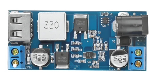
The HCW-P715 is a high-efficiency buck converter designed for stepping down DC voltage while increasing current. This compact and reliable DC-DC converter is ideal for applications requiring efficient power management, such as battery-powered devices, embedded systems, and industrial electronics. Its high switching frequency and robust design make it a versatile choice for engineers and hobbyists alike.
Explore Projects Built with Buck Converter HCW-P715


Explore Projects Built with Buck Converter HCW-P715
Common Applications and Use Cases
- Powering microcontrollers and sensors from higher voltage sources
- Voltage regulation in battery-powered devices
- Step-down voltage conversion for LED drivers
- Power supply for portable electronics
- Industrial automation systems
Technical Specifications
Key Technical Details
| Parameter | Value |
|---|---|
| Input Voltage Range | 4.5V to 28V |
| Output Voltage Range | 0.8V to 20V |
| Maximum Output Current | 5A |
| Efficiency | Up to 95% |
| Switching Frequency | 150 kHz to 1 MHz |
| Operating Temperature | -40°C to +85°C |
| Dimensions | 22mm x 17mm x 4mm |
Pin Configuration and Descriptions
| Pin Number | Pin Name | Description |
|---|---|---|
| 1 | VIN | Input voltage pin (connect to DC power source). |
| 2 | GND | Ground pin (common ground for input and output). |
| 3 | VOUT | Output voltage pin (regulated DC output). |
| 4 | EN | Enable pin (active high to enable the converter). |
| 5 | FB | Feedback pin (used for voltage regulation). |
Usage Instructions
How to Use the HCW-P715 in a Circuit
Connect the Input Voltage (VIN):
Attach the positive terminal of your DC power source to theVINpin and the negative terminal to theGNDpin. Ensure the input voltage is within the specified range (4.5V to 28V).Set the Output Voltage (VOUT):
Use an external resistor divider connected to theFBpin to set the desired output voltage. Refer to the formula provided in the datasheet to calculate the resistor values.Enable the Converter:
Connect theENpin to a high logic level (e.g., 3.3V or 5V) to enable the converter. If unused, tie theENpin toVINthrough a pull-up resistor.Connect the Load:
Attach your load to theVOUTpin and ensure the load current does not exceed the maximum output current of 5A.Add External Components:
Place appropriate input and output capacitors close to theVINandVOUTpins to ensure stable operation. Refer to the datasheet for recommended capacitor values.
Important Considerations and Best Practices
- Thermal Management: Ensure adequate heat dissipation, especially when operating at high currents. Use a heatsink or place the module in a well-ventilated area if necessary.
- Input Voltage Range: Do not exceed the maximum input voltage of 28V to avoid damaging the module.
- Output Voltage Adjustment: Double-check the resistor divider values to ensure the output voltage is within the desired range.
- Decoupling Capacitors: Use low-ESR capacitors for input and output filtering to minimize noise and ripple.
Example: Using HCW-P715 with Arduino UNO
The HCW-P715 can be used to power an Arduino UNO from a higher voltage source, such as a 12V battery. Below is an example circuit and Arduino code to demonstrate its usage:
Circuit Setup
- Connect the
VINpin of the HCW-P715 to the positive terminal of the 12V battery. - Connect the
GNDpin of the HCW-P715 to the negative terminal of the battery. - Set the output voltage to 5V using the resistor divider.
- Connect the
VOUTpin of the HCW-P715 to the5Vpin of the Arduino UNO. - Connect the
GNDpin of the HCW-P715 to theGNDpin of the Arduino UNO.
Arduino Code Example
// Example code to blink an LED using Arduino UNO powered by HCW-P715
// Ensure the HCW-P715 output is set to 5V before connecting to Arduino

const int ledPin = 13; // Pin connected to the onboard LED

void setup() {
  pinMode(ledPin, OUTPUT); // Set the LED pin as an output
}

void loop() {
  digitalWrite(ledPin, HIGH); // Turn the LED on
  delay(1000);               // Wait for 1 second
  digitalWrite(ledPin, LOW);  // Turn the LED off
  delay(1000);               // Wait for 1 second
}
Troubleshooting and FAQs
Common Issues and Solutions
No Output Voltage:
- Ensure the
ENpin is connected to a high logic level. - Verify the input voltage is within the specified range.
- Check for loose connections or damaged components.
- Ensure the
Output Voltage is Incorrect:
- Double-check the resistor divider values connected to the
FBpin. - Ensure the load does not exceed the maximum current rating.
- Double-check the resistor divider values connected to the
Excessive Heat Generation:
- Verify the input and output voltages are within the specified range.
- Use a heatsink or improve ventilation to dissipate heat.
High Output Ripple:
- Add low-ESR capacitors to the input and output pins.
- Ensure proper grounding and minimize the length of connecting wires.
FAQs
Q: Can the HCW-P715 be used with a 24V input to power a 5V device?
A: Yes, the HCW-P715 supports input voltages up to 28V and can step down to 5V. Ensure proper resistor divider values are used to set the output voltage.
Q: What is the maximum load current the HCW-P715 can handle?
A: The HCW-P715 can handle a maximum output current of 5A. Exceeding this limit may damage the module.
Q: Do I need to use an external heatsink?
A: A heatsink is recommended if the module operates at high currents or in environments with poor ventilation.
Q: Can I use the HCW-P715 to power an Arduino Nano?
A: Yes, the HCW-P715 can be used to power an Arduino Nano. Set the output voltage to 5V or 3.3V, depending on the Nano's requirements.