How to Use Power Inverter: Examples, Pinouts, and Specs
Introduction
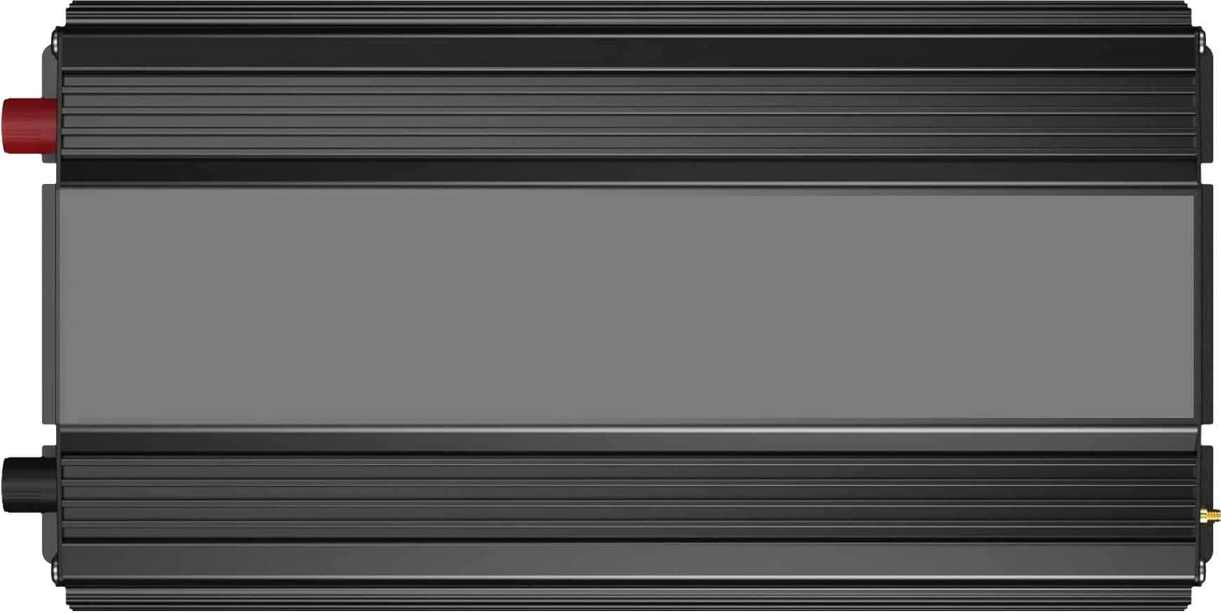
The VOLTWORKS Store ETL UL458 12V DC to 110V 120V AC 1000W Power Inverter is a high-performance device designed to convert direct current (DC) from a 12V battery source into alternating current (AC) at 110V or 120V. This inverter is commonly used in applications such as solar power systems, uninterruptible power supplies (UPS), and various off-grid power solutions. It provides a reliable and efficient way to power AC devices using a DC power source.
Explore Projects Built with Power Inverter
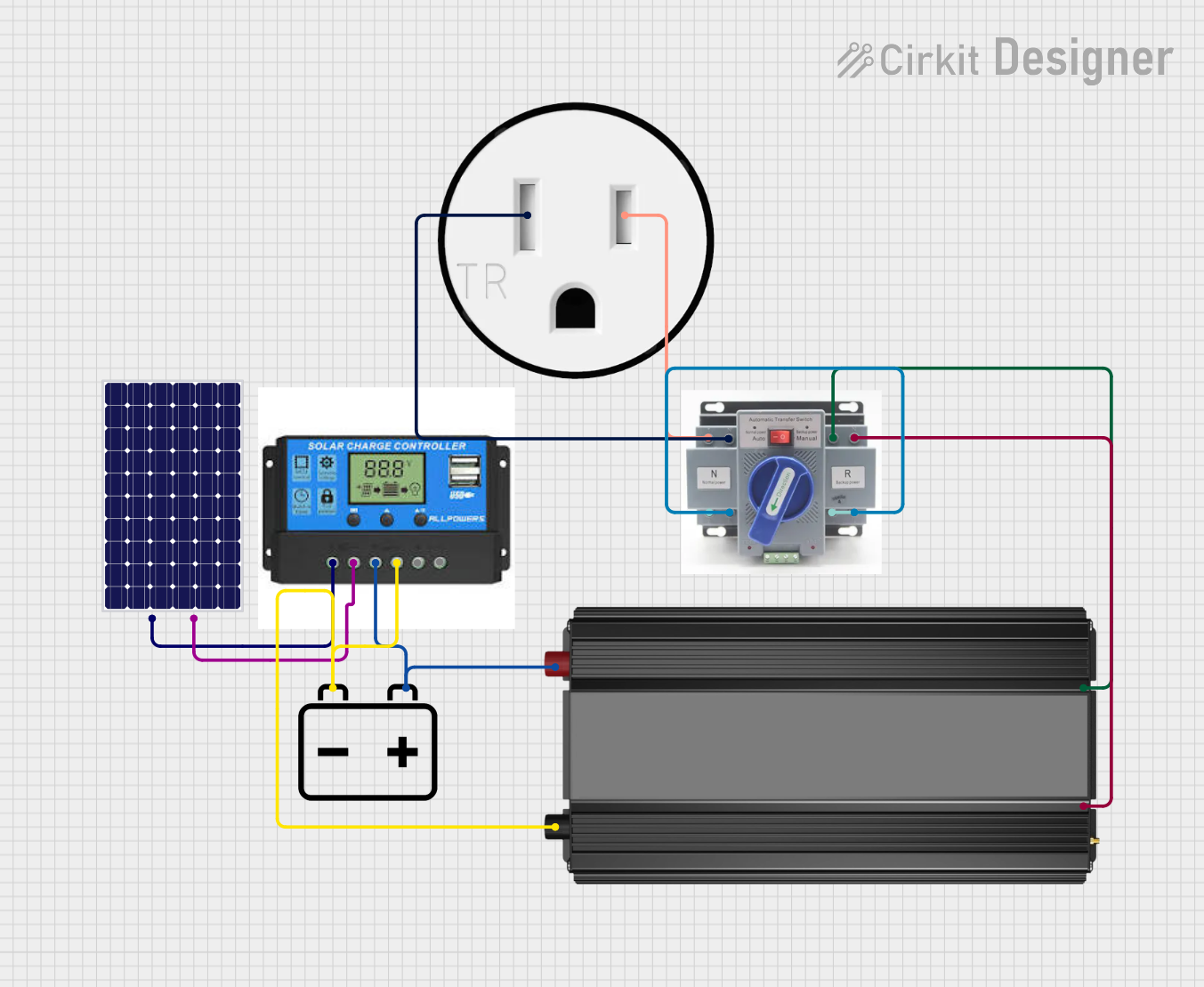

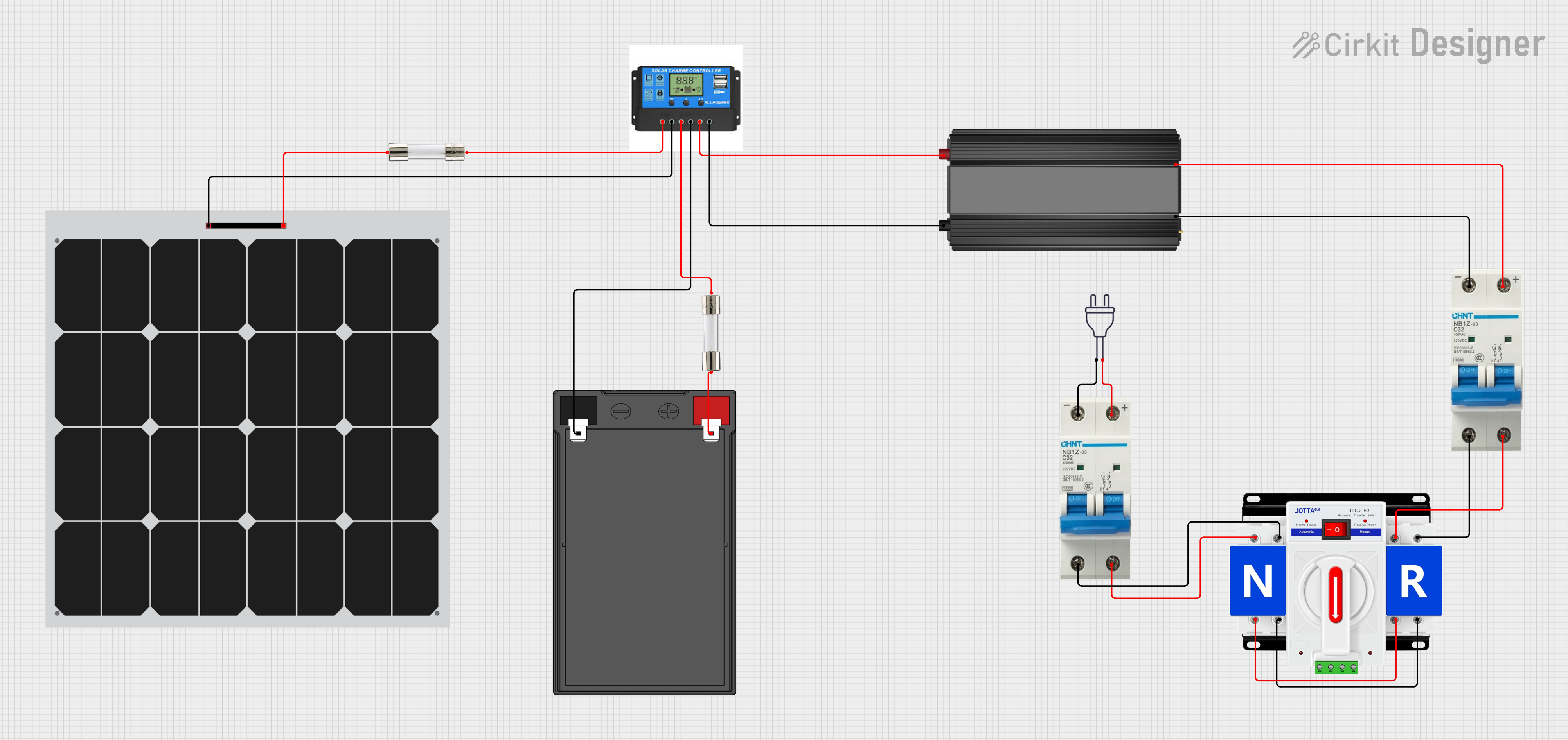
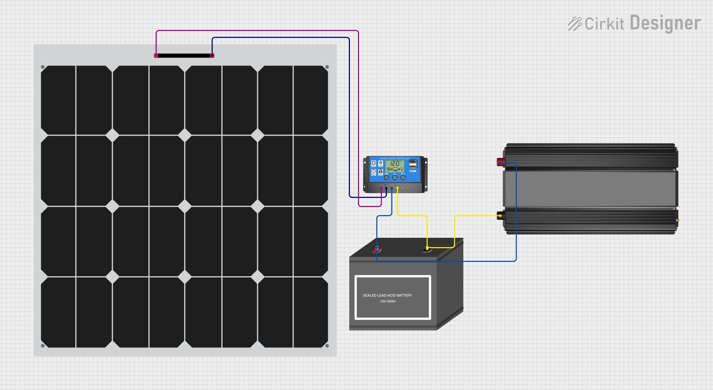
Explore Projects Built with Power Inverter
Technical Specifications
Key Technical Details
| Parameter | Specification |
|---|---|
| Input Voltage | 12V DC |
| Output Voltage | 110V/120V AC |
| Continuous Power Output | 1000W |
| Peak Power Output | 2000W |
| Output Waveform | Modified Sine Wave |
| Efficiency | Up to 90% |
| No Load Current Draw | < 1.0A |
| USB Output | 5V DC, 2.1A |
| Protection Features | Overload, Over-temperature, Short Circuit, Low Voltage, Over Voltage |
Pin Configuration and Descriptions
| Pin Number | Pin Name | Description |
|---|---|---|
| 1 | Positive Input | Connect to the positive terminal of the 12V battery |
| 2 | Negative Input | Connect to the negative terminal of the 12V battery |
| 3 | AC Output | Provides 110V/120V AC output for connected devices |
| 4 | USB Output | Provides 5V DC output for USB-powered devices |
| 5 | Ground | Connect to the ground for safety and stability |
Usage Instructions
How to Use the Component in a Circuit
Connect the Inverter to the Battery:
- Connect the positive input pin of the inverter to the positive terminal of the 12V battery.
- Connect the negative input pin of the inverter to the negative terminal of the 12V battery.
Connect AC Devices:
- Plug your AC devices into the AC output socket of the inverter.
Connect USB Devices:
- If you have USB-powered devices, connect them to the USB output port.
Power On:
- Turn on the inverter using the power switch. The inverter will start converting DC to AC, and your connected devices will receive power.
Important Considerations and Best Practices
Ensure Proper Ventilation:
- Place the inverter in a well-ventilated area to prevent overheating.
Avoid Overloading:
- Do not exceed the continuous power output rating of 1000W. Overloading can damage the inverter and connected devices.
Check Battery Voltage:
- Ensure the battery voltage is within the specified range (12V). Low or high voltage can trigger protection features and shut down the inverter.
Use Proper Cables:
- Use cables with appropriate gauge to handle the current draw. Undersized cables can cause voltage drops and overheating.
Troubleshooting and FAQs
Common Issues Users Might Face
Inverter Not Powering On:
- Solution: Check the battery connections and ensure the battery voltage is within the specified range. Verify that the power switch is turned on.
Low Output Voltage:
- Solution: Ensure the battery is fully charged. Check for any loose connections or undersized cables.
Overload Protection Triggered:
- Solution: Reduce the load by disconnecting some devices. Ensure the total power consumption does not exceed 1000W.
Over-temperature Protection Triggered:
- Solution: Improve ventilation around the inverter. Allow the inverter to cool down before restarting.
FAQs
Q: Can I use this inverter with a solar panel system?
- A: Yes, this inverter is suitable for use with solar panel systems. Ensure the solar panel system includes a charge controller to regulate the battery charging.
Q: Is the output waveform suitable for sensitive electronics?
- A: The inverter provides a modified sine wave output, which is suitable for most household appliances. However, for sensitive electronics, a pure sine wave inverter is recommended.
Q: How do I know if the inverter is overloaded?
- A: The inverter has an overload protection feature. If overloaded, it will shut down automatically. Reduce the load and restart the inverter.
Q: Can I connect the inverter to an Arduino UNO?
- A: While the inverter itself is not directly connected to an Arduino UNO, you can use the AC output to power devices that are part of an Arduino project. Ensure proper isolation and safety measures are in place.
By following this documentation, users can effectively utilize the VOLTWORKS Store ETL UL458 12V DC to 110V 120V AC 1000W Power Inverter in various applications, ensuring safe and efficient operation.