Cirkit Designer Logo
Cirkit Designer
Your all-in-one circuit design IDE
Home / 
Component Documentation

How to Use ICM-45686: Examples, Pinouts, and Specs

Image of ICM-45686
Cirkit Designer LogoDesign with ICM-45686 in Cirkit Designer

Introduction

The ICM-45686 is a high-performance integrated circuit (IC) manufactured by TDM InvenSense. It is designed for precision measurement and control applications, offering high accuracy, low power consumption, and robust performance. This IC is particularly well-suited for interfacing with various sensors, making it ideal for applications in industrial automation, robotics, IoT devices, and wearable technology.

Explore Projects Built with ICM-45686

Use Cirkit Designer to design, explore, and prototype these projects online. Some projects support real-time simulation. Click "Open Project" to start designing instantly!
Battery-Powered Emergency Alert System with NUCLEO-F072RB, SIM800L, and GPS NEO 6M
Image of women safety: A project utilizing ICM-45686 in a practical application
This circuit is an emergency alert system that uses a NUCLEO-F072RB microcontroller to send SMS alerts and make calls via a SIM800L GSM module, while obtaining location data from a GPS NEO 6M module. The system is powered by a Li-ion battery and includes a TP4056 module for battery charging and protection, with a rocker switch to control power to the microcontroller.
Cirkit Designer LogoOpen Project in Cirkit Designer
Satellite-Based Timing and Navigation System with SDR and Atomic Clock Synchronization
Image of GPS 시스템 측정 구성도_Confirm: A project utilizing ICM-45686 in a practical application
This circuit appears to be a complex system involving power supply management, GPS and timing synchronization, and data communication. It includes a SI-TEX G1 Satellite Compass for GPS data, an XHTF1021 Atomic Rubidium Clock for precise timing, and Ettus USRP B200 units for software-defined radio communication. Power is supplied through various SMPS units and distributed via terminal blocks and DC jacks. Data communication is facilitated by Beelink MINI S12 N95 computers, RS232 splitters, and a 1000BASE-T Media Converter for network connectivity. RF Directional Couplers are used to interface antennas with the USRP units, and the entire system is likely contained within cases for protection and organization.
Cirkit Designer LogoOpen Project in Cirkit Designer
ESP8266 and SIM800L Based GPS Tracker with I2C LCD Display and Battery Power
Image of Little Innovator Competition: A project utilizing ICM-45686 in a practical application
This circuit integrates an ESP8266 NodeMCU microcontroller with a SIM800L GSM module, a GPS NEO 6M module, and a 16x2 I2C LCD display for communication and location tracking. It also includes a pushbutton for user input, a piezo buzzer for audio alerts, and is powered by a 2x 18650 battery pack through an LM2596 step-down module.
Cirkit Designer LogoOpen Project in Cirkit Designer
Cellular-Enabled IoT Device with Real-Time Clock and Power Management
Image of LRCM PHASE 2 BASIC: A project utilizing ICM-45686 in a practical application
This circuit features a LilyGo-SIM7000G module for cellular communication and GPS functionality, interfaced with an RTC DS3231 for real-time clock capabilities. It includes voltage sensing through two voltage sensor modules, and uses an 8-channel opto-coupler for isolating different parts of the circuit. Power management is handled by a buck converter connected to a DC power source and batteries, with a fuse for protection and a rocker switch for on/off control. Additionally, there's an LED for indication purposes.
Cirkit Designer LogoOpen Project in Cirkit Designer

Explore Projects Built with ICM-45686

Use Cirkit Designer to design, explore, and prototype these projects online. Some projects support real-time simulation. Click "Open Project" to start designing instantly!
Image of women safety: A project utilizing ICM-45686 in a practical application
Battery-Powered Emergency Alert System with NUCLEO-F072RB, SIM800L, and GPS NEO 6M
This circuit is an emergency alert system that uses a NUCLEO-F072RB microcontroller to send SMS alerts and make calls via a SIM800L GSM module, while obtaining location data from a GPS NEO 6M module. The system is powered by a Li-ion battery and includes a TP4056 module for battery charging and protection, with a rocker switch to control power to the microcontroller.
Cirkit Designer LogoOpen Project in Cirkit Designer
Image of GPS 시스템 측정 구성도_Confirm: A project utilizing ICM-45686 in a practical application
Satellite-Based Timing and Navigation System with SDR and Atomic Clock Synchronization
This circuit appears to be a complex system involving power supply management, GPS and timing synchronization, and data communication. It includes a SI-TEX G1 Satellite Compass for GPS data, an XHTF1021 Atomic Rubidium Clock for precise timing, and Ettus USRP B200 units for software-defined radio communication. Power is supplied through various SMPS units and distributed via terminal blocks and DC jacks. Data communication is facilitated by Beelink MINI S12 N95 computers, RS232 splitters, and a 1000BASE-T Media Converter for network connectivity. RF Directional Couplers are used to interface antennas with the USRP units, and the entire system is likely contained within cases for protection and organization.
Cirkit Designer LogoOpen Project in Cirkit Designer
Image of Little Innovator Competition: A project utilizing ICM-45686 in a practical application
ESP8266 and SIM800L Based GPS Tracker with I2C LCD Display and Battery Power
This circuit integrates an ESP8266 NodeMCU microcontroller with a SIM800L GSM module, a GPS NEO 6M module, and a 16x2 I2C LCD display for communication and location tracking. It also includes a pushbutton for user input, a piezo buzzer for audio alerts, and is powered by a 2x 18650 battery pack through an LM2596 step-down module.
Cirkit Designer LogoOpen Project in Cirkit Designer
Image of LRCM PHASE 2 BASIC: A project utilizing ICM-45686 in a practical application
Cellular-Enabled IoT Device with Real-Time Clock and Power Management
This circuit features a LilyGo-SIM7000G module for cellular communication and GPS functionality, interfaced with an RTC DS3231 for real-time clock capabilities. It includes voltage sensing through two voltage sensor modules, and uses an 8-channel opto-coupler for isolating different parts of the circuit. Power management is handled by a buck converter connected to a DC power source and batteries, with a fuse for protection and a rocker switch for on/off control. Additionally, there's an LED for indication purposes.
Cirkit Designer LogoOpen Project in Cirkit Designer

Common Applications

  • Sensor interfacing for industrial and consumer electronics
  • Motion tracking in robotics and drones
  • Environmental monitoring systems
  • Wearable devices for health and fitness tracking
  • IoT devices requiring precise measurement and control

Technical Specifications

Key Technical Details

Parameter Value
Manufacturer TDM InvenSense
Part Number ICM-45686
Operating Voltage Range 1.8V to 3.6V
Power Consumption Ultra-low power (typical: 0.5 mA)
Sensor Interfaces I2C, SPI
Operating Temperature -40°C to +85°C
Package Type 3x3 mm LGA (Land Grid Array)
Features High accuracy, low noise, integrated FIFO

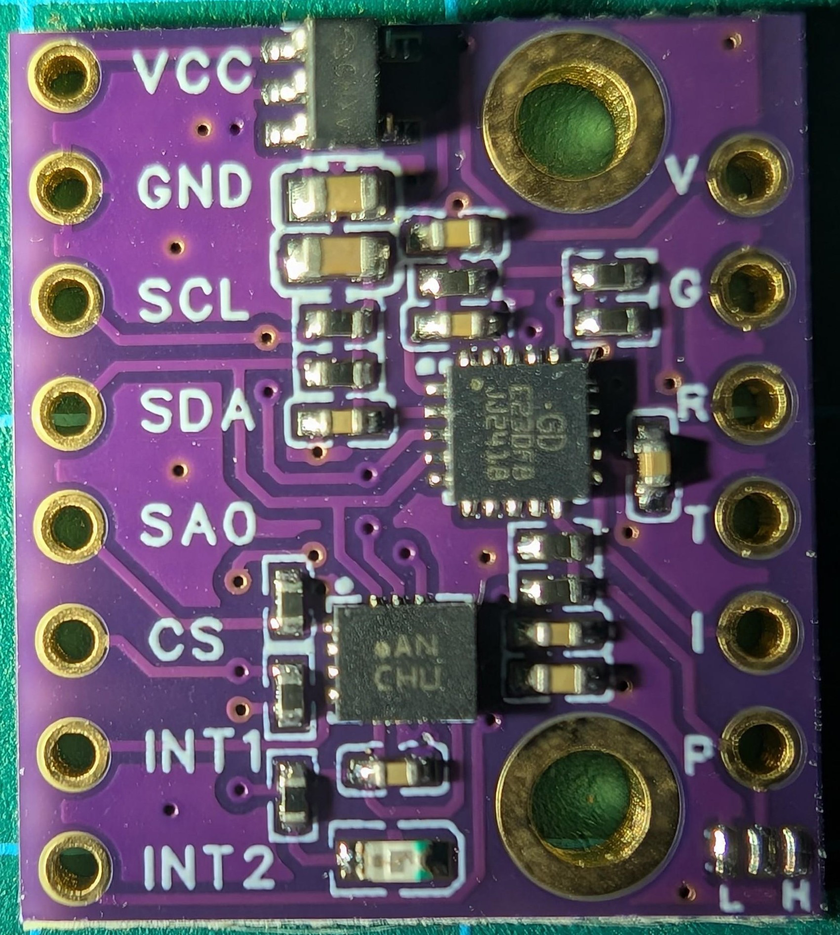
Pin Configuration and Descriptions

The ICM-45686 comes in a compact 3x3 mm LGA package with the following pin configuration:

Pin Number Pin Name Description
1 VDD Power supply input (1.8V to 3.6V)
2 GND Ground
3 SCL I2C clock input / SPI clock input
4 SDA/SDI I2C data input/output / SPI data input
5 SDO SPI data output
6 INT Interrupt output
7 FSYNC Frame synchronization input
8 RESV Reserved (leave unconnected)

Usage Instructions

How to Use the ICM-45686 in a Circuit

  1. Power Supply: Connect the VDD pin to a regulated power source (1.8V to 3.6V) and the GND pin to the ground.
  2. Communication Interface: Choose between I2C or SPI for communication:
    • For I2C, connect the SCL and SDA pins to the corresponding lines on your microcontroller.
    • For SPI, connect SCL (SPI clock), SDA/SDI (SPI data input), and SDO (SPI data output) to the appropriate SPI pins on your microcontroller.
  3. Interrupts: Use the INT pin to receive interrupt signals for events such as data availability or errors.
  4. Frame Synchronization: Optionally, use the FSYNC pin for synchronizing data acquisition with an external signal.
  5. Pull-Up Resistors: For I2C communication, ensure pull-up resistors (typically 4.7 kΩ) are connected to the SCL and SDA lines.

Important Considerations

  • Power Supply Decoupling: Place a 0.1 µF ceramic capacitor close to the VDD pin to reduce noise.
  • Unused Pins: Leave the RESV pin unconnected.
  • Startup Time: Allow sufficient time for the IC to initialize after power-up (refer to the datasheet for exact timing).
  • Communication Protocol: Ensure the microcontroller's I2C or SPI settings match the ICM-45686's requirements.

Example Code for Arduino UNO (I2C Communication)

#include <Wire.h> // Include the Wire library for I2C communication

#define ICM45686_ADDR 0x68 // I2C address of the ICM-45686

void setup() {
  Wire.begin(); // Initialize I2C communication
  Serial.begin(9600); // Initialize serial communication for debugging

  // Configure the ICM-45686
  Wire.beginTransmission(ICM45686_ADDR);
  Wire.write(0x6B); // Register address for power management
  Wire.write(0x00); // Set to normal mode
  Wire.endTransmission();

  Serial.println("ICM-45686 initialized.");
}

void loop() {
  // Read data from the ICM-45686
  Wire.beginTransmission(ICM45686_ADDR);
  Wire.write(0x3B); // Register address for sensor data
  Wire.endTransmission(false);
  Wire.requestFrom(ICM45686_ADDR, 6); // Request 6 bytes of data

  if (Wire.available() == 6) {
    int16_t accelX = (Wire.read() << 8) | Wire.read(); // Combine high and low bytes
    int16_t accelY = (Wire.read() << 8) | Wire.read();
    int16_t accelZ = (Wire.read() << 8) | Wire.read();

    Serial.print("Accel X: "); Serial.print(accelX);
    Serial.print(" Y: "); Serial.print(accelY);
    Serial.print(" Z: "); Serial.println(accelZ);
  }

  delay(500); // Wait for 500 ms before the next reading
}

Troubleshooting and FAQs

Common Issues and Solutions

  1. No Communication with the IC

    • Cause: Incorrect I2C address or wiring.
    • Solution: Verify the I2C address (default: 0x68) and check all connections.
  2. High Noise in Sensor Data

    • Cause: Insufficient power supply decoupling or noisy environment.
    • Solution: Add a 0.1 µF capacitor near the VDD pin and ensure proper grounding.
  3. Interrupt Pin Not Responding

    • Cause: Interrupts not enabled in the IC configuration.
    • Solution: Check the configuration registers and enable the required interrupts.
  4. Device Overheating

    • Cause: Exceeding the operating voltage range.
    • Solution: Ensure the power supply is within the 1.8V to 3.6V range.

FAQs

  • Q: Can the ICM-45686 operate at 5V?
    A: No, the maximum operating voltage is 3.6V. Exceeding this may damage the IC.

  • Q: What is the maximum data rate for I2C communication?
    A: The ICM-45686 supports I2C speeds up to 400 kHz (Fast Mode).

  • Q: Is the IC suitable for battery-powered devices?
    A: Yes, its ultra-low power consumption makes it ideal for battery-powered applications.

  • Q: Can I use the ICM-45686 with a 3.3V microcontroller?
    A: Yes, the IC is compatible with 3.3V logic levels.

This concludes the documentation for the ICM-45686. For further details, refer to the official datasheet provided by TDM InvenSense.