How to Use 5 CHANNEL FLAME SENSOR: Examples, Pinouts, and Specs
Introduction
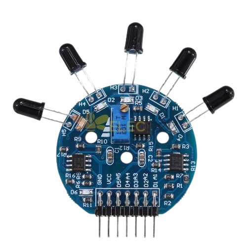
The 5 Channel Flame Sensor is a device designed to detect the presence of flames or fire by sensing infrared (IR) light emitted by flames. It features five independent flame detection sensors, which provide a wide detection range and improved accuracy. This multi-sensor design reduces false alarms and ensures reliable operation in various environments. The sensor is commonly used in fire detection systems, industrial safety systems, and robotics applications where flame detection is critical.
Explore Projects Built with 5 CHANNEL FLAME SENSOR
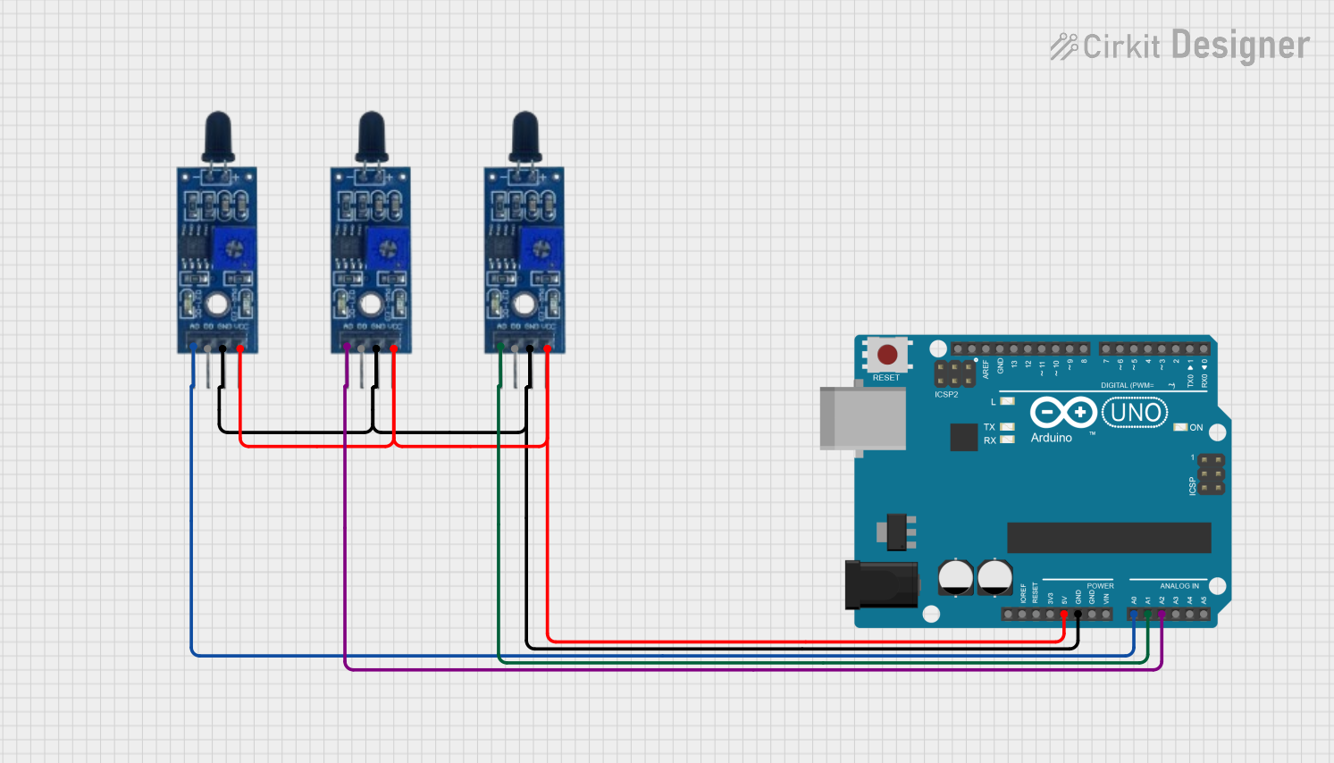
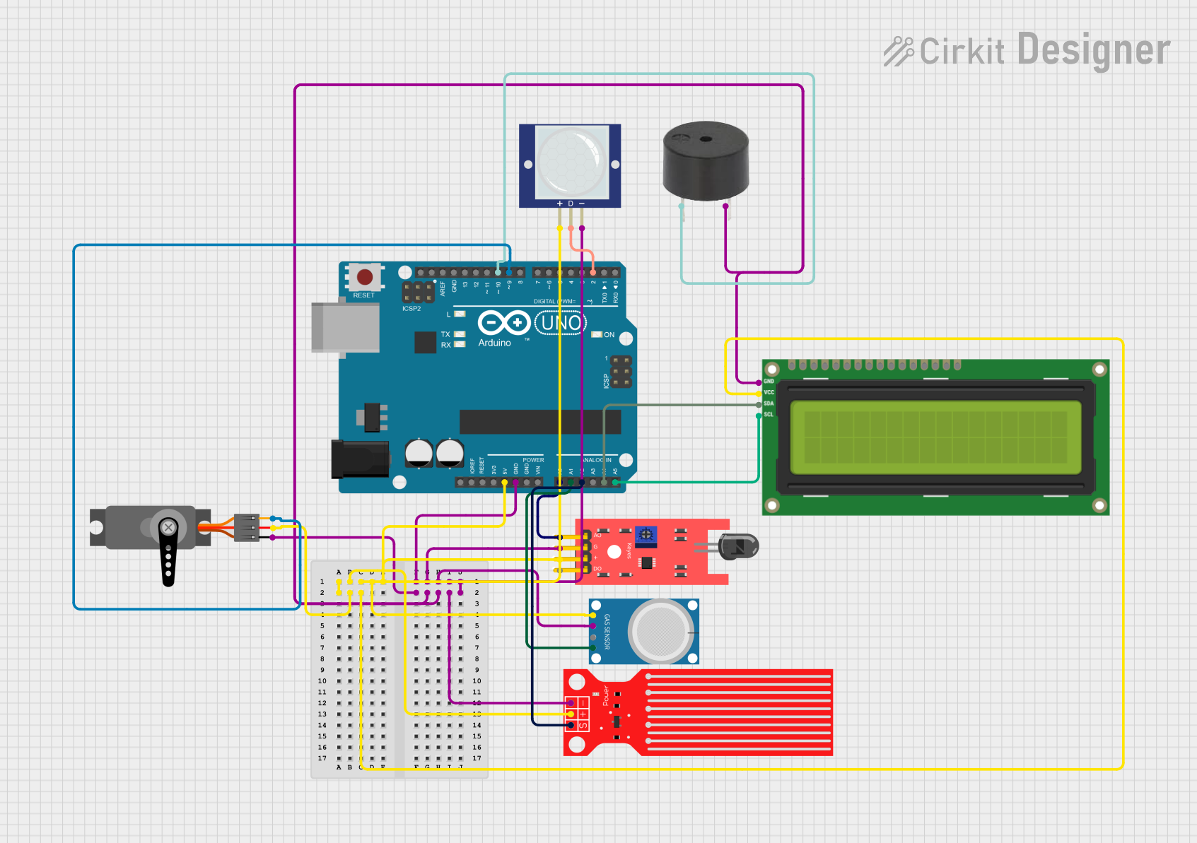
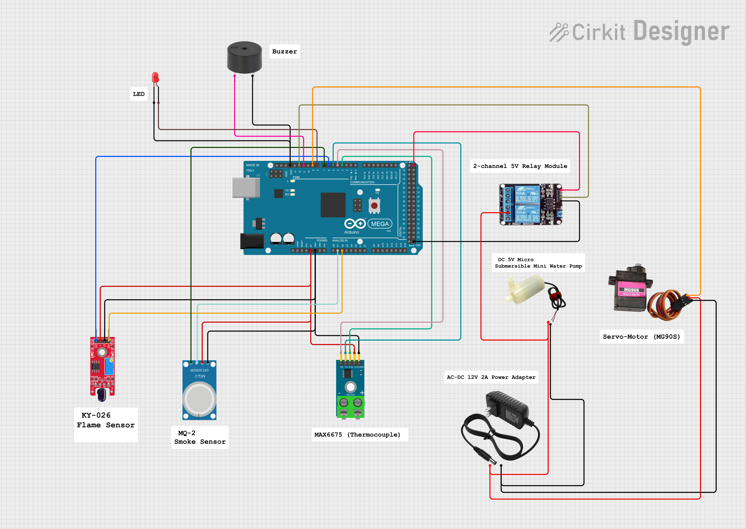
Explore Projects Built with 5 CHANNEL FLAME SENSOR
Common Applications and Use Cases
- Fire detection and alarm systems
- Industrial safety monitoring
- Robotics and autonomous systems for fire detection
- Commercial safety systems in kitchens, factories, and warehouses
- Educational projects and experiments involving flame detection
Technical Specifications
The 5 Channel Flame Sensor is designed for easy integration into electronic systems. Below are its key technical details:
General Specifications
| Parameter | Value |
|---|---|
| Operating Voltage | 3.3V to 5V |
| Detection Range | 0° to 60° per sensor |
| Wavelength Sensitivity | 760 nm to 1100 nm (IR spectrum) |
| Output Type | Digital and Analog |
| Response Time | ≤ 15 ms |
| Operating Temperature | -25°C to 85°C |
| Dimensions | Varies by manufacturer (e.g., 50mm x 20mm) |
Pin Configuration and Descriptions
The 5 Channel Flame Sensor typically has the following pin layout:
| Pin Number | Pin Name | Description |
|---|---|---|
| 1 | VCC | Power supply input (3.3V to 5V) |
| 2 | GND | Ground connection |
| 3 | D1 | Digital output for Sensor 1 (HIGH when flame is detected) |
| 4 | D2 | Digital output for Sensor 2 (HIGH when flame is detected) |
| 5 | D3 | Digital output for Sensor 3 (HIGH when flame is detected) |
| 6 | D4 | Digital output for Sensor 4 (HIGH when flame is detected) |
| 7 | D5 | Digital output for Sensor 5 (HIGH when flame is detected) |
| 8 | AOUT | Analog output (combined signal from all sensors for precise flame intensity) |
Usage Instructions
How to Use the Component in a Circuit
- Power the Sensor: Connect the
VCCpin to a 3.3V or 5V power source and theGNDpin to ground. - Connect Outputs:
- Use the
D1toD5pins for individual digital outputs from each sensor. These pins will output HIGH (logic 1) when a flame is detected. - Use the
AOUTpin for an analog signal that represents the combined flame intensity detected by all sensors.
- Use the
- Read Outputs:
- For digital outputs, connect the
D1toD5pins to digital input pins on a microcontroller (e.g., Arduino). - For analog output, connect the
AOUTpin to an analog input pin on the microcontroller.
- For digital outputs, connect the
Important Considerations and Best Practices
- Placement: Ensure the sensor is positioned with a clear line of sight to the flame source. Avoid obstructions that may block IR light.
- Power Supply: Use a stable power supply to avoid noise in the sensor readings.
- Environmental Factors: The sensor may be affected by strong ambient IR sources (e.g., sunlight). Use shielding or filters if necessary.
- Testing: Test the sensor in the intended environment to ensure reliable operation and adjust the sensitivity if required (some models include a potentiometer for sensitivity adjustment).
Example Code for Arduino UNO
The following code demonstrates how to use the 5 Channel Flame Sensor with an Arduino UNO to detect flames and display the results in the Serial Monitor.
// Define digital pins for the 5 flame sensor outputs
#define FLAME_SENSOR_1 2
#define FLAME_SENSOR_2 3
#define FLAME_SENSOR_3 4
#define FLAME_SENSOR_4 5
#define FLAME_SENSOR_5 6

void setup() {
  // Initialize serial communication
  Serial.begin(9600);

  // Set flame sensor pins as inputs
  pinMode(FLAME_SENSOR_1, INPUT);
  pinMode(FLAME_SENSOR_2, INPUT);
  pinMode(FLAME_SENSOR_3, INPUT);
  pinMode(FLAME_SENSOR_4, INPUT);
  pinMode(FLAME_SENSOR_5, INPUT);
}

void loop() {
  // Read the state of each flame sensor
  int flame1 = digitalRead(FLAME_SENSOR_1);
  int flame2 = digitalRead(FLAME_SENSOR_2);
  int flame3 = digitalRead(FLAME_SENSOR_3);
  int flame4 = digitalRead(FLAME_SENSOR_4);
  int flame5 = digitalRead(FLAME_SENSOR_5);

  // Print the sensor states to the Serial Monitor
  Serial.print("Sensor 1: "); Serial.println(flame1);
  Serial.print("Sensor 2: "); Serial.println(flame2);
  Serial.print("Sensor 3: "); Serial.println(flame3);
  Serial.print("Sensor 4: "); Serial.println(flame4);
  Serial.print("Sensor 5: "); Serial.println(flame5);
  Serial.println("-----------------------");

  // Add a short delay for readability
  delay(500);
}
Troubleshooting and FAQs
Common Issues and Solutions
No Detection of Flames:
- Ensure the sensor is powered correctly (check
VCCandGNDconnections). - Verify that the flame is within the sensor's detection range and angle.
- Check for obstructions or environmental factors (e.g., strong ambient IR light).
- Ensure the sensor is powered correctly (check
False Alarms:
- Reduce sensitivity using the onboard potentiometer (if available).
- Shield the sensor from external IR sources like sunlight or heat lamps.
Unstable Readings:
- Use a stable power supply to minimize noise.
- Add a capacitor across the power supply pins to filter out voltage fluctuations.
FAQs
Q: Can the sensor detect flames through glass?
A: No, most glass materials block IR light, so the sensor may not detect flames through glass.
Q: What is the maximum detection distance?
A: The detection distance depends on the flame size and intensity but typically ranges from 0.8m to 1.5m.
Q: Can I use this sensor outdoors?
A: While the sensor can operate outdoors, it may require shielding from sunlight and weatherproofing for reliable performance.
Q: How do I adjust the sensitivity?
A: Some models include a potentiometer for sensitivity adjustment. Turn it clockwise to increase sensitivity and counterclockwise to decrease it.