How to Use Teensy 4.1+: Examples, Pinouts, and Specs
Introduction
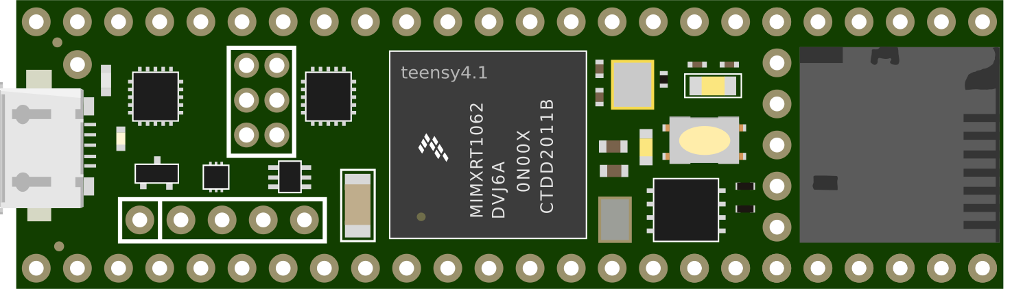
The Teensy 4.1+ is a high-performance microcontroller board powered by a 600 MHz ARM Cortex-M7 processor. It is designed for demanding applications requiring significant processing power, such as audio processing, real-time data acquisition, robotics, and advanced IoT systems. The Teensy 4.1+ offers extensive connectivity options, including Ethernet, USB host, and multiple serial interfaces, making it a versatile choice for developers. It is fully compatible with the Arduino IDE, allowing for easy programming and integration into existing projects.
Explore Projects Built with Teensy 4.1+
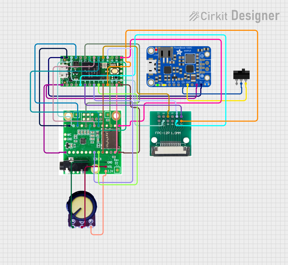
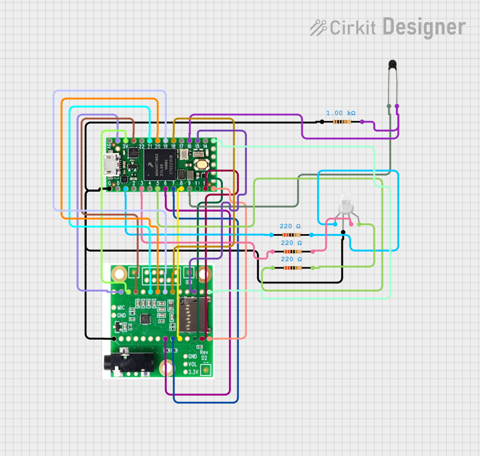
Explore Projects Built with Teensy 4.1+
Common Applications and Use Cases
- Audio synthesis and digital signal processing (DSP)
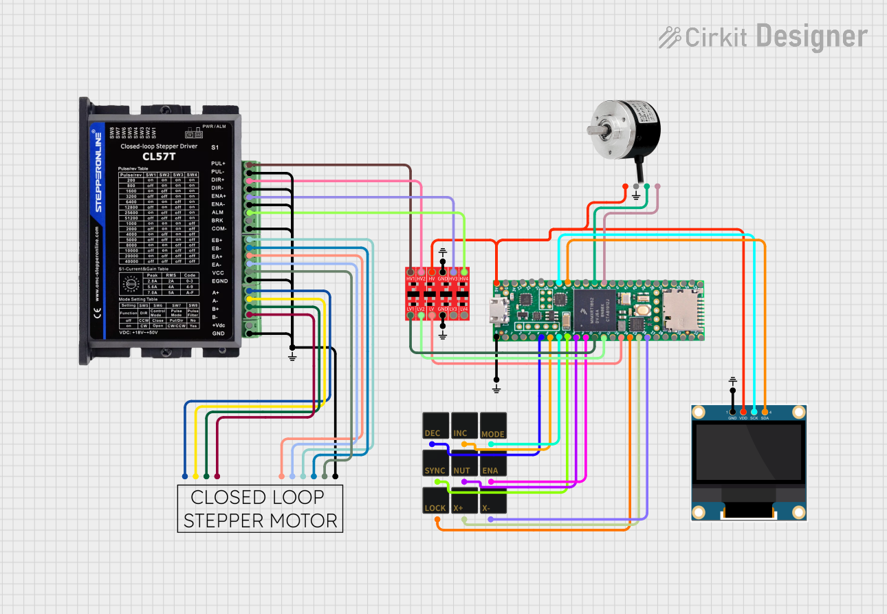
- Robotics and motor control
- High-speed data acquisition and logging
- IoT devices with Ethernet or USB connectivity
- Advanced sensor fusion and machine learning applications
- Real-time control systems
Technical Specifications
Key Technical Details
| Specification | Value |
|---|---|
| Processor | ARM Cortex-M7, 600 MHz |
| Flash Memory | 8 MB (expandable via QSPI) |
| RAM | 1024 KB (1 MB) |
| External Memory Support | SD card slot, QSPI flash support |
| Operating Voltage | 3.3V |
| Input Voltage Range | 3.6V to 5.5V |
| Digital I/O Pins | 55 |
| Analog Input Pins | 14 (12-bit ADC) |
| PWM Pins | 35 |
| Communication Interfaces | UART, SPI, I2C, CAN, Ethernet |
| USB | USB 2.0 (Host and Device modes) |
| Dimensions | 2.4 x 0.7 inches (61 x 18 mm) |
Pin Configuration and Descriptions
The Teensy 4.1+ features a total of 55 digital I/O pins, with multiple functions assigned to each pin. Below is a summary of the pin configuration:
| Pin Number | Function(s) | Description |
|---|---|---|
| 0-13 | Digital I/O, PWM | General-purpose digital pins with PWM |
| 14-23 | Analog Input, Digital I/O | 12-bit ADC and digital functionality |
| 24-33 | Digital I/O, SPI, I2C | SPI and I2C communication support |
| 34-39 | Digital I/O, CAN | CAN bus communication |
| 40-55 | Digital I/O, Ethernet, USB | Ethernet and USB host/device interfaces |
For a complete pinout diagram, refer to the official Teensy 4.1+ documentation.
Usage Instructions
How to Use the Teensy 4.1+ in a Circuit
Powering the Board:
- The Teensy 4.1+ can be powered via the USB port (5V) or an external power supply (3.6V to 5.5V). Ensure the power source is stable and within the specified range.
Connecting Peripherals:
- Use the digital and analog pins to connect sensors, actuators, and other peripherals. For communication, utilize the UART, SPI, I2C, or CAN interfaces as needed.
Programming the Board:
- Install the Arduino IDE and the Teensyduino add-on. Select "Teensy 4.1" as the board type in the IDE. Write your code and upload it via the USB connection.
Using the SD Card Slot:
- Insert a microSD card into the onboard slot for data logging or file storage. Use the
SDlibrary in Arduino to interact with the card.
- Insert a microSD card into the onboard slot for data logging or file storage. Use the
Important Considerations and Best Practices
- Voltage Levels: The Teensy 4.1+ operates at 3.3V logic levels. Ensure all connected devices are compatible or use level shifters.
- Heat Management: For intensive applications, consider adding a heatsink to the processor to prevent overheating.
- Pin Protection: Avoid applying voltages higher than 3.3V to the I/O pins to prevent damage.
- Ethernet Usage: To use the Ethernet interface, connect an external Ethernet PHY module to the dedicated pins.
Example Code: Blinking an LED
Below is an example of how to blink an LED connected to pin 13:
// This example blinks an LED connected to pin 13 on the Teensy 4.1+.
// The LED will turn on for 1 second and off for 1 second in a loop.

void setup() {
  pinMode(13, OUTPUT); // Set pin 13 as an output
}

void loop() {
  digitalWrite(13, HIGH); // Turn the LED on
  delay(1000);            // Wait for 1 second
  digitalWrite(13, LOW);  // Turn the LED off
  delay(1000);            // Wait for 1 second
}
Example Code: Reading an Analog Sensor
Here is an example of reading an analog sensor connected to pin A0:
// This example reads the value of an analog sensor connected to pin A0
// and prints the value to the Serial Monitor.

void setup() {
  Serial.begin(9600); // Initialize serial communication at 9600 baud
}

void loop() {
  int sensorValue = analogRead(A0); // Read the analog value from pin A0
  Serial.println(sensorValue);      // Print the value to the Serial Monitor
  delay(500);                       // Wait for 500 milliseconds
}
Troubleshooting and FAQs
Common Issues and Solutions
The board is not recognized by the computer:
- Ensure the USB cable is data-capable (not charge-only).
- Check that the Teensyduino add-on is installed in the Arduino IDE.
- Press the reset button on the Teensy 4.1+ to force it into programming mode.
Code does not upload:
- Verify that "Teensy 4.1" is selected as the board type in the Arduino IDE.
- Ensure no other program is using the COM port assigned to the Teensy.
Peripherals are not working as expected:
- Double-check the wiring and connections.
- Confirm that the peripherals are compatible with 3.3V logic levels.
- Use a multimeter to verify power and signal integrity.
Ethernet is not functioning:
- Ensure the Ethernet PHY module is correctly connected to the dedicated pins.
- Use the
Ethernetlibrary in Arduino and verify the configuration.
FAQs
Can I use 5V sensors with the Teensy 4.1+?
Yes, but you will need level shifters to convert the 5V signals to 3.3V.What is the maximum SD card size supported?
The Teensy 4.1+ supports SD cards up to 128 GB, formatted as FAT32 or exFAT.Can I use the Teensy 4.1+ without the Arduino IDE?
Yes, you can use other development environments like PlatformIO or write bare-metal code.Does the Teensy 4.1+ support Wi-Fi?
No, but you can add Wi-Fi functionality using external modules like the ESP8266 or ESP32.
This concludes the documentation for the Teensy 4.1+. For further details, refer to the official Teensy website and community forums.