How to Use esp32-WROOM-32e: Examples, Pinouts, and Specs
Introduction
The ESP32-WROOM-32E is a powerful Wi-Fi and Bluetooth microcontroller module manufactured by Freenove. It features dual-core processing, making it ideal for a wide range of IoT (Internet of Things) applications. With its integrated antenna, low power consumption, and robust connectivity options, the ESP32-WROOM-32E is a versatile solution for projects requiring wireless communication and efficient processing.
Explore Projects Built with esp32-WROOM-32e


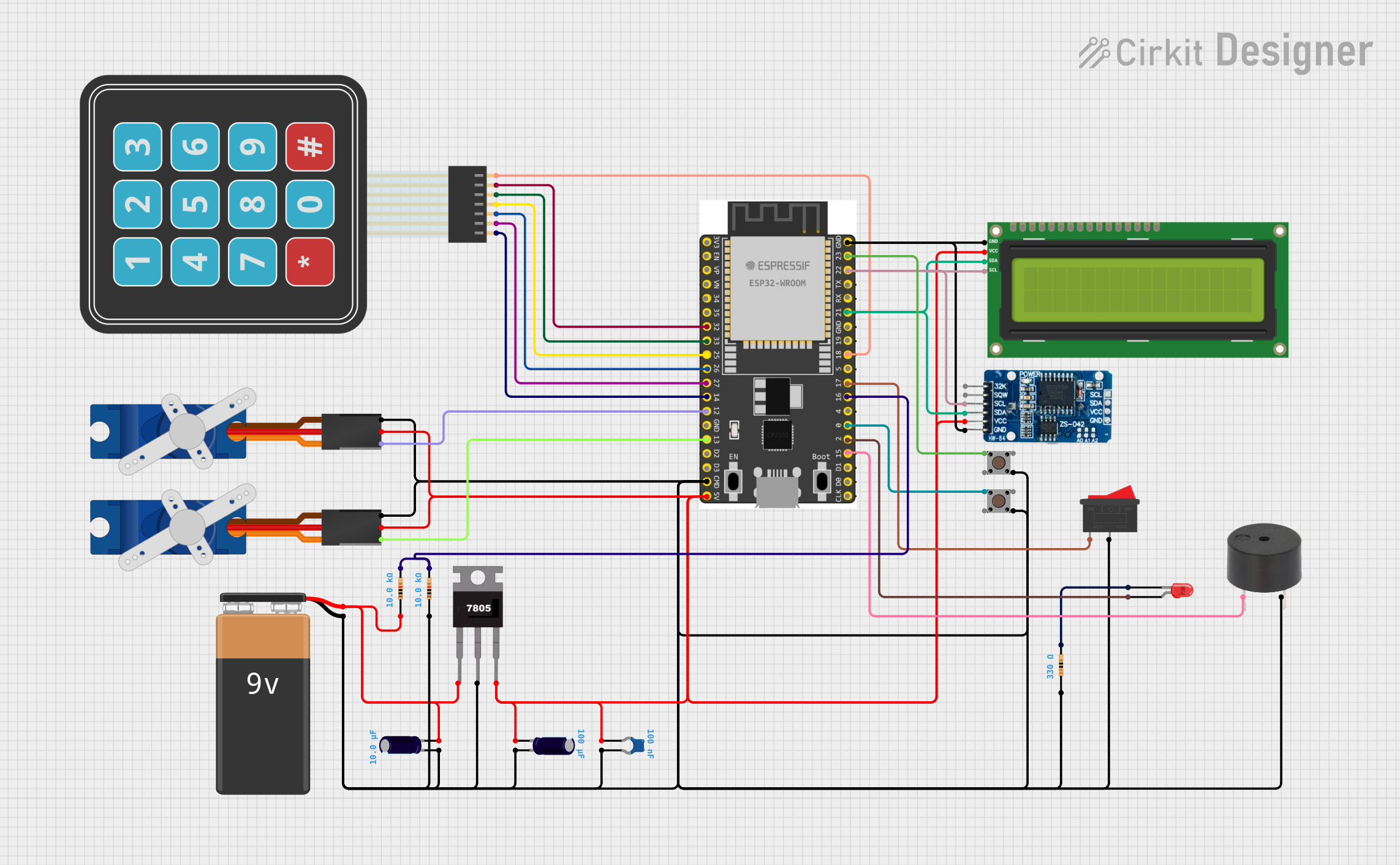
Explore Projects Built with esp32-WROOM-32e
Common Applications and Use Cases
- Smart home devices (e.g., smart lights, thermostats, and security systems)
- Industrial IoT systems for monitoring and control
- Wearable devices with wireless connectivity
- Wireless sensor networks
- Robotics and automation
- Prototyping and development of IoT solutions
Technical Specifications
The ESP32-WROOM-32E module is designed to deliver high performance while maintaining energy efficiency. Below are its key technical details:
Key Technical Details
- Processor: Dual-core Xtensa® 32-bit LX6 microprocessor
- Clock Speed: Up to 240 MHz
- Wireless Connectivity:
- Wi-Fi: 802.11 b/g/n (2.4 GHz)
- Bluetooth: v4.2 BR/EDR and BLE
- Flash Memory: 4 MB
- Operating Voltage: 3.0V to 3.6V
- Operating Temperature: -40°C to 85°C
- GPIO Pins: 34 (multipurpose, including ADC, DAC, PWM, I2C, SPI, UART)
- Power Consumption:
- Deep Sleep: ~10 µA
- Active Mode: ~240 mA (Wi-Fi active)
- Integrated Antenna: PCB antenna
- Dimensions: 18 mm x 25.5 mm x 3.1 mm
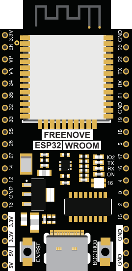
Pin Configuration and Descriptions
The ESP32-WROOM-32E module has a total of 38 pins. Below is a table describing the key pins:
| Pin Name | Type | Description |
|---|---|---|
| 3V3 | Power | 3.3V power input |
| GND | Power | Ground |
| EN | Input | Enable pin (active high) |
| IO0 | GPIO/Boot Mode | GPIO0, used to enter bootloader mode when pulled low during reset |
| IO2 | GPIO | General-purpose input/output |
| IO4 | GPIO | General-purpose input/output |
| IO12 | GPIO/ADC | GPIO12, can also function as an ADC input |
| IO13 | GPIO/ADC | GPIO13, can also function as an ADC input |
| IO14 | GPIO/PWM | GPIO14, supports PWM output |
| IO15 | GPIO/PWM | GPIO15, supports PWM output |
| IO16 | GPIO/UART | GPIO16, can also function as a UART pin |
| IO17 | GPIO/UART | GPIO17, can also function as a UART pin |
| IO18 | GPIO/SPI | GPIO18, supports SPI communication |
| IO19 | GPIO/SPI | GPIO19, supports SPI communication |
| IO21 | GPIO/I2C | GPIO21, supports I2C communication (SDA) |
| IO22 | GPIO/I2C | GPIO22, supports I2C communication (SCL) |
| IO23 | GPIO/SPI | GPIO23, supports SPI communication |
| IO25 | GPIO/DAC | GPIO25, can also function as a DAC output |
| IO26 | GPIO/DAC | GPIO26, can also function as a DAC output |
| IO27 | GPIO/ADC | GPIO27, can also function as an ADC input |
| IO32 | GPIO/ADC | GPIO32, can also function as an ADC input |
| IO33 | GPIO/ADC | GPIO33, can also function as an ADC input |
| IO34 | GPIO/ADC | GPIO34, input-only ADC pin |
| IO35 | GPIO/ADC | GPIO35, input-only ADC pin |
| TXD0 | UART | UART0 transmit pin |
| RXD0 | UART | UART0 receive pin |
Usage Instructions
The ESP32-WROOM-32E is a versatile module that can be used in a variety of circuits. Below are the steps and best practices for using the module effectively:
How to Use the Component in a Circuit
- Power Supply: Connect the 3V3 pin to a stable 3.3V power source and GND to ground.
- Boot Mode: To upload code, connect GPIO0 to GND and reset the module. After uploading, disconnect GPIO0 from GND.
- Programming: Use a USB-to-serial adapter to connect the module to your computer. Connect TXD0 to the adapter's RX pin, RXD0 to the adapter's TX pin, and GND to the adapter's ground.
- Peripherals: Connect sensors, actuators, or other peripherals to the GPIO pins as needed. Ensure the voltage levels are compatible with the ESP32's 3.3V logic.
Important Considerations and Best Practices
- Voltage Levels: Avoid applying voltages higher than 3.3V to the GPIO pins to prevent damage.
- Power Supply: Use a low-noise, stable power source to ensure reliable operation.
- Antenna Placement: Ensure the integrated antenna is not obstructed by metal objects or enclosures to maintain good wireless performance.
- Deep Sleep Mode: Use deep sleep mode to conserve power in battery-powered applications.
Example Code for Arduino UNO
The ESP32-WROOM-32E can be programmed using the Arduino IDE. Below is an example of how to connect the module to a Wi-Fi network:
#include <WiFi.h> // Include the Wi-Fi library for ESP32

const char* ssid = "Your_SSID";       // Replace with your Wi-Fi network name
const char* password = "Your_Password"; // Replace with your Wi-Fi password

void setup() {
  Serial.begin(115200); // Initialize serial communication at 115200 baud
  delay(1000);          // Wait for a moment to stabilize

  Serial.println("Connecting to Wi-Fi...");
  WiFi.begin(ssid, password); // Start connecting to the Wi-Fi network

  while (WiFi.status() != WL_CONNECTED) {
    delay(500); // Wait for connection
    Serial.print(".");
  }

  Serial.println("\nConnected to Wi-Fi!");
  Serial.print("IP Address: ");
  Serial.println(WiFi.localIP()); // Print the assigned IP address
}

void loop() {
  // Add your main code here
}
Troubleshooting and FAQs
Common Issues and Solutions
Module Not Responding:
- Ensure the module is powered correctly (3.3V on the 3V3 pin).
- Check the connections to the USB-to-serial adapter.
- Verify that GPIO0 is connected to GND during programming.
Wi-Fi Connection Fails:
- Double-check the SSID and password in your code.
- Ensure the Wi-Fi network is within range and not overloaded.
Unstable Operation:
- Use a stable power supply with sufficient current capacity.
- Avoid placing the module near sources of electromagnetic interference.
FAQs
Q: Can the ESP32-WROOM-32E operate on 5V?
A: No, the module operates on 3.3V. Applying 5V to the power or GPIO pins may damage the module.Q: How do I reset the module?
A: Pull the EN pin low momentarily to reset the module.Q: Can I use the ESP32-WROOM-32E with the Arduino IDE?
A: Yes, the module is fully compatible with the Arduino IDE. Install the ESP32 board package to get started.Q: What is the maximum range of the Wi-Fi connection?
A: The range depends on the environment but typically extends up to 100 meters in open spaces.