Cirkit Designer
Your all-in-one circuit design IDE
Home /
Component Documentation
How to Use ADU: Examples, Pinouts, and Specs
Introduction
The ADU is an Analog-to-Digital Converter (ADC) designed to convert analog signals into digital data for processing in digital systems. This component is essential in bridging the gap between the analog world and digital electronics, enabling microcontrollers, processors, and other digital devices to interpret real-world signals such as temperature, pressure, sound, and light.
Explore Projects Built with ADU
Arduino UNO Based Fall Detection System with GSM Alert
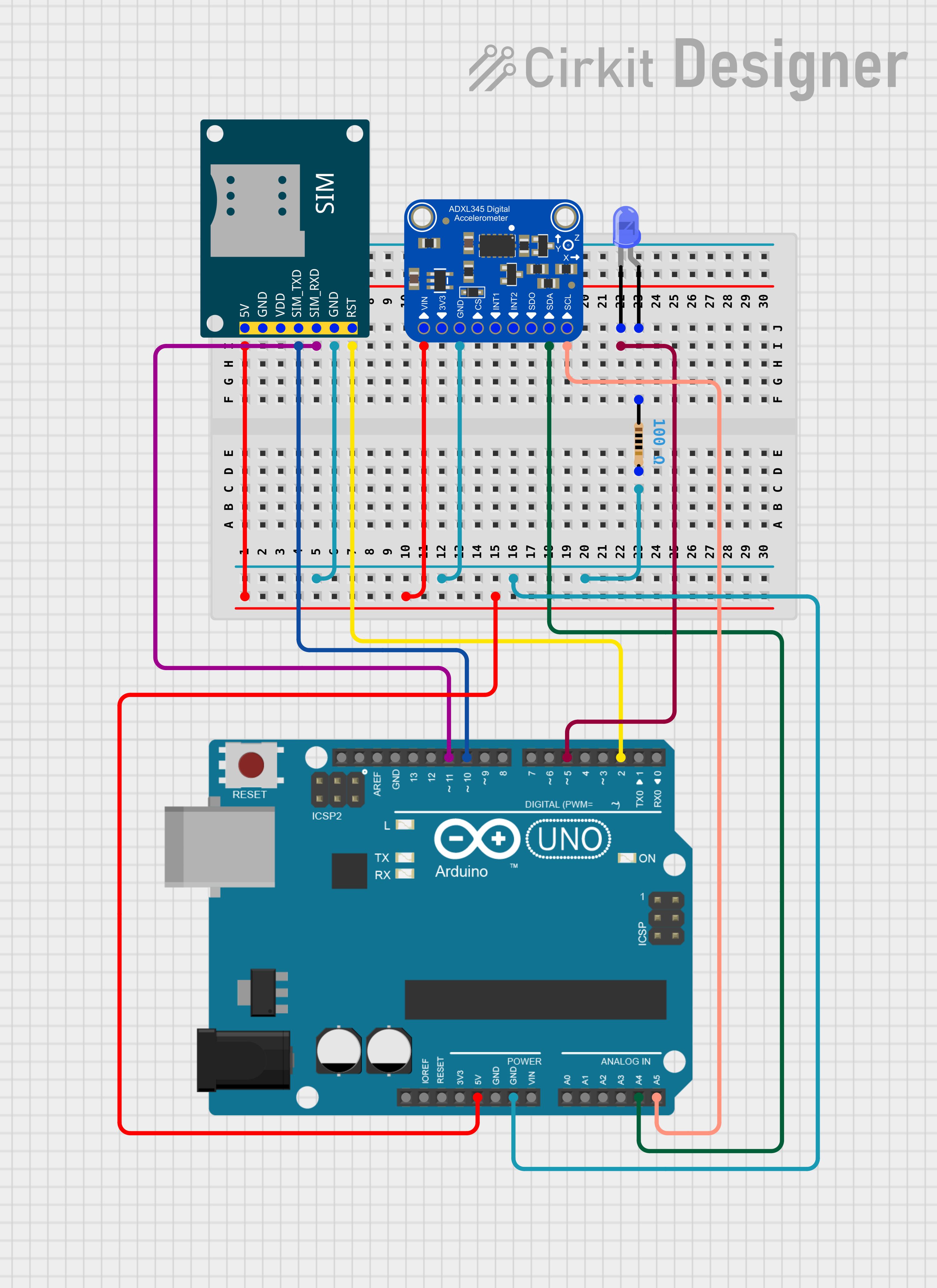
This circuit features an Arduino UNO microcontroller interfaced with an Adafruit ADXL345 accelerometer and a SIM800L GSM module. The Arduino monitors the accelerometer for a fall detection event and uses the GSM module to send an SMS alert when a fall is detected. Additionally, there is a blue LED connected through a resistor that could be used for status indication.
Arduino UNO-Based Smart Helmet with Alcohol Detection and Emergency Alert System
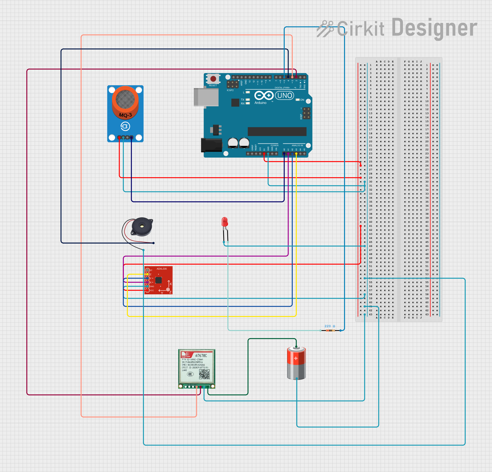
This circuit is a safety system for a helmet that uses an Arduino UNO to monitor alcohol levels and detect emergencies. It includes an MQ-3 alcohol sensor, an ADXL335 accelerometer, a GSM module for sending SOS messages, a buzzer, and an LED for alerts. The system activates the buzzer and sends an SOS message if high alcohol levels or sudden impacts are detected.
Arduino UNO Controlled Dual DC Motor Driver with ADXL335 Accelerometer Feedback
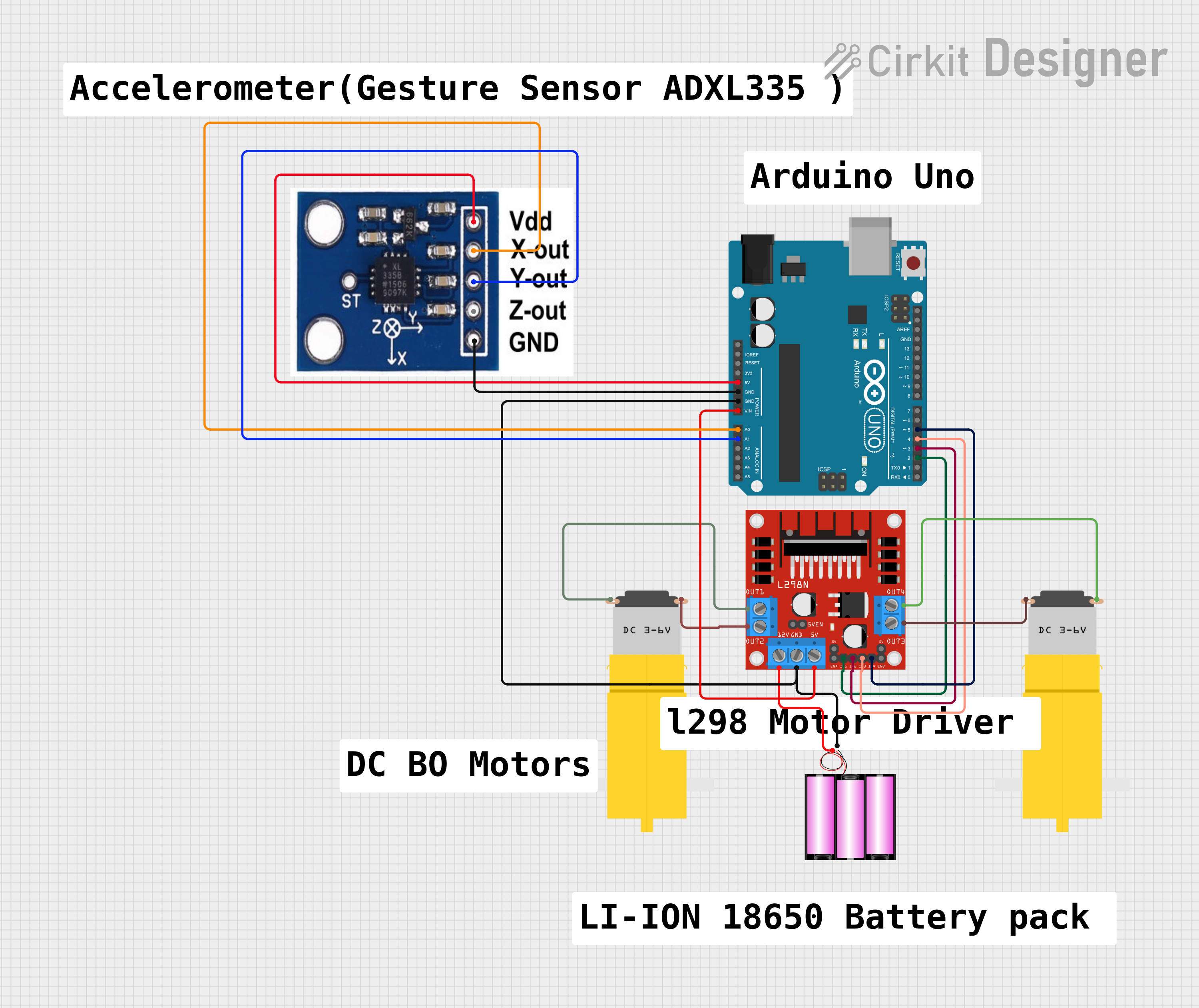
This circuit features an Arduino UNO microcontroller interfaced with an ADXXL335 accelerometer and an L298N DC motor driver. The accelerometer's outputs are connected to the Arduino's analog inputs for motion sensing, while the motor driver is controlled by the Arduino's digital outputs to manage two DC motors. A 12V battery provides power to the motor driver and the Arduino, with the latter also supplying 5V to the accelerometer.
Arduino UNO Based Fall Detection System with SMS Alerts Using ADXL345 and SIM800L

This circuit features an Arduino UNO microcontroller interfaced with an Adafruit ADXL345 accelerometer and a SIM800L GSM module for communication. The Arduino monitors the accelerometer for a fall detection event and uses the GSM module to send an SMS alert when a fall is detected. Additionally, there is a blue LED with a series resistor, potentially used as a status indicator.
Explore Projects Built with ADU
Arduino UNO Based Fall Detection System with GSM Alert
This circuit features an Arduino UNO microcontroller interfaced with an Adafruit ADXL345 accelerometer and a SIM800L GSM module. The Arduino monitors the accelerometer for a fall detection event and uses the GSM module to send an SMS alert when a fall is detected. Additionally, there is a blue LED connected through a resistor that could be used for status indication.
Arduino UNO-Based Smart Helmet with Alcohol Detection and Emergency Alert System
This circuit is a safety system for a helmet that uses an Arduino UNO to monitor alcohol levels and detect emergencies. It includes an MQ-3 alcohol sensor, an ADXL335 accelerometer, a GSM module for sending SOS messages, a buzzer, and an LED for alerts. The system activates the buzzer and sends an SOS message if high alcohol levels or sudden impacts are detected.
Arduino UNO Controlled Dual DC Motor Driver with ADXL335 Accelerometer Feedback
This circuit features an Arduino UNO microcontroller interfaced with an ADXXL335 accelerometer and an L298N DC motor driver. The accelerometer's outputs are connected to the Arduino's analog inputs for motion sensing, while the motor driver is controlled by the Arduino's digital outputs to manage two DC motors. A 12V battery provides power to the motor driver and the Arduino, with the latter also supplying 5V to the accelerometer.
Arduino UNO Based Fall Detection System with SMS Alerts Using ADXL345 and SIM800L
This circuit features an Arduino UNO microcontroller interfaced with an Adafruit ADXL345 accelerometer and a SIM800L GSM module for communication. The Arduino monitors the accelerometer for a fall detection event and uses the GSM module to send an SMS alert when a fall is detected. Additionally, there is a blue LED with a series resistor, potentially used as a status indicator.
Common Applications and Use Cases
- Sensor data acquisition (e.g., temperature, pressure, and light sensors)
- Audio signal processing
- Data logging systems
- Industrial automation and control systems
- Medical devices (e.g., ECG and EEG machines)
Technical Specifications
The ADU is a versatile ADC with the following key specifications:
| Parameter | Value |
|---|---|
| Resolution | 10-bit, 12-bit, or 16-bit options |
| Input Voltage Range | 0V to 5V |
| Sampling Rate | Up to 200 kSPS (kilo-samples per second) |
| Supply Voltage | 2.7V to 5.5V |
| Power Consumption | Low power (typical: 1.5 mW) |
| Communication Interface | SPI or I2C |
| Operating Temperature | -40°C to +85°C |
Pin Configuration and Descriptions
Below is the pinout for the ADU:
| Pin Name | Pin Number | Description |
|---|---|---|
| VDD | 1 | Positive power supply (2.7V to 5.5V) |
| GND | 2 | Ground |
| VREF | 3 | Reference voltage input |
| AIN+ | 4 | Positive analog input |
| AIN- | 5 | Negative analog input (for differential mode) |
| SCLK | 6 | Serial clock input (SPI mode) |
| SDI/SDA | 7 | Serial data input (SPI) or data line (I2C mode) |
| SDO/ADDR | 8 | Serial data output (SPI) or address select (I2C) |
| CS | 9 | Chip select (active low, SPI mode only) |
| NC | 10 | No connection |
Usage Instructions
How to Use the ADU in a Circuit
- Power Supply: Connect the VDD pin to a stable power source (2.7V to 5.5V) and the GND pin to ground.
- Reference Voltage: Provide a stable reference voltage to the VREF pin. This determines the ADC's input range.
- Analog Input: Connect the analog signal to the AIN+ pin. For differential mode, connect the complementary signal to AIN-.
- Communication Interface:
- For SPI: Connect SCLK, SDI, SDO, and CS to the corresponding pins on your microcontroller.
- For I2C: Connect SDA and SCL to the microcontroller's I2C pins.
- Bypass Capacitor: Place a 0.1 µF capacitor close to the VDD pin to reduce noise.
Important Considerations and Best Practices
- Ensure the reference voltage (VREF) is stable and noise-free for accurate conversions.
- Use proper decoupling capacitors to minimize power supply noise.
- Avoid exceeding the input voltage range (0V to VREF) to prevent damage to the ADC.
- For high-speed applications, ensure the SPI or I2C clock frequency is within the ADC's supported range.
Example Code for Arduino UNO (SPI Mode)
#include <SPI.h>

// Define ADC pins
const int CS_PIN = 10; // Chip select pin for the ADU

void setup() {
  // Initialize SPI communication
  SPI.begin();
  pinMode(CS_PIN, OUTPUT);
  digitalWrite(CS_PIN, HIGH); // Set CS pin high to deselect the ADC

  Serial.begin(9600); // Initialize serial communication for debugging
}

void loop() {
  uint16_t adcValue = readADC(); // Read ADC value
  float voltage = (adcValue * 5.0) / 1023.0; // Convert to voltage (assuming 10-bit ADC)

  Serial.print("ADC Value: ");
  Serial.print(adcValue);
  Serial.print(" | Voltage: ");
  Serial.println(voltage, 3); // Print voltage with 3 decimal places

  delay(500); // Wait for 500ms before the next reading
}

uint16_t readADC() {
  digitalWrite(CS_PIN, LOW); // Select the ADC
  delayMicroseconds(1); // Small delay for stability

  // Send and receive data over SPI
  uint8_t highByte = SPI.transfer(0x00); // Send dummy byte to receive high byte
  uint8_t lowByte = SPI.transfer(0x00);  // Send dummy byte to receive low byte

  digitalWrite(CS_PIN, HIGH); // Deselect the ADC

  // Combine high and low bytes into a 16-bit value
  return (highByte << 8) | lowByte;
}
Troubleshooting and FAQs
Common Issues
No Output or Incorrect Readings
- Cause: Improper wiring or loose connections.
- Solution: Double-check all connections, especially power, ground, and communication lines.
Noisy or Fluctuating Readings
- Cause: Unstable reference voltage or noisy power supply.
- Solution: Use a low-noise voltage regulator and proper decoupling capacitors.
Communication Failure
- Cause: Incorrect SPI or I2C configuration.
- Solution: Verify the clock frequency, data format, and pin connections.
FAQs
Can the ADU handle negative input voltages?
- No, the input voltage must remain within the range of 0V to VREF.
What is the maximum sampling rate?
- The ADU supports sampling rates up to 200 kSPS, depending on the resolution and configuration.
Can I use the ADU with a 3.3V microcontroller?
- Yes, as long as the supply voltage (VDD) and logic levels are compatible with the microcontroller.
How do I select between SPI and I2C modes?
- The mode is determined by the wiring and configuration of the SDO/ADDR pin. Refer to the datasheet for details.