How to Use RedBot MainBoard: Examples, Pinouts, and Specs
Introduction
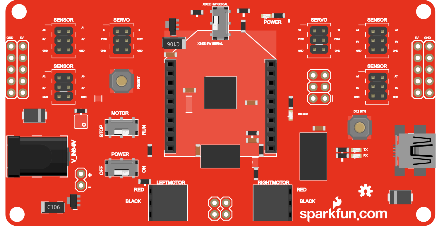
The RedBot MainBoard is a versatile and user-friendly robotic platform designed to serve as the central unit for building and controlling small robots. It integrates motor drivers, a built-in accelerometer, and line following sensors, making it an ideal choice for educational purposes, hobbyists, and prototype development. Common applications include autonomous vehicles, educational robots, and hobbyist robotic projects.
Explore Projects Built with RedBot MainBoard
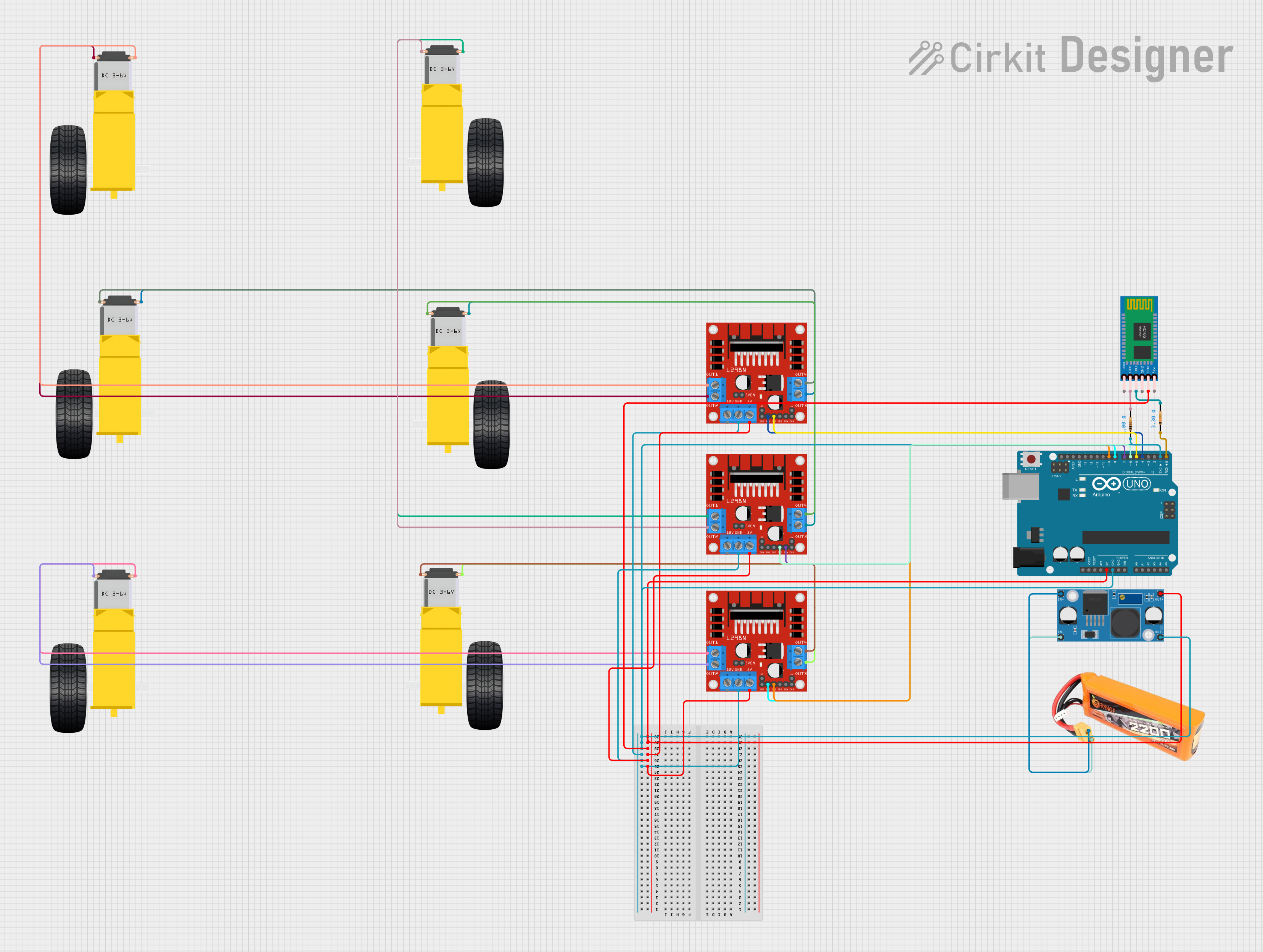
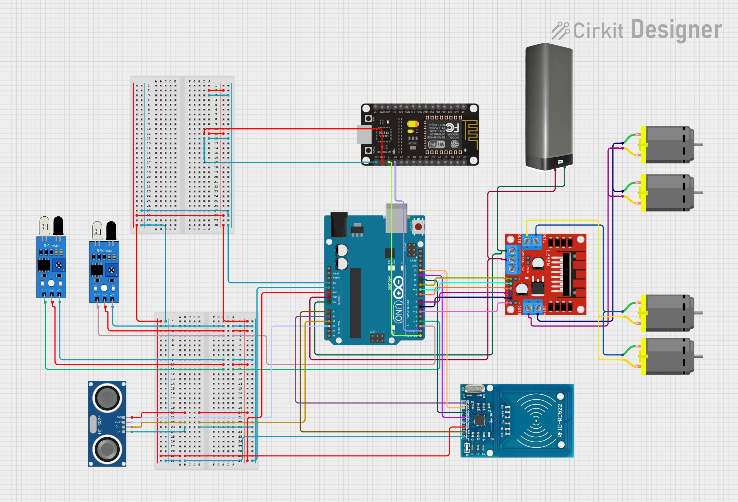
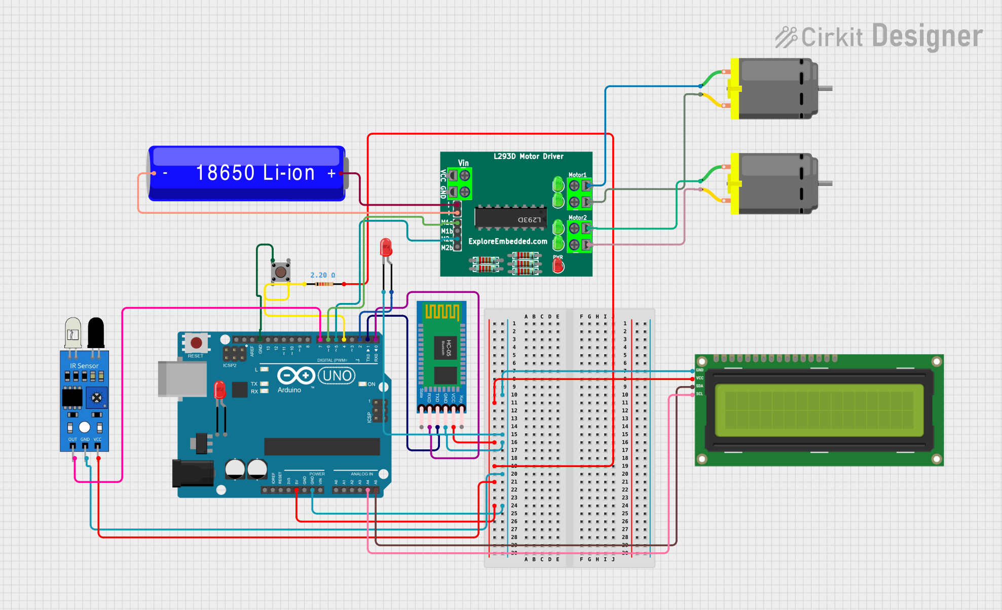

Explore Projects Built with RedBot MainBoard
Technical Specifications
Key Technical Details
- Microcontroller: ATmega328P
- Operating Voltage: 6V to 9V recommended
- Motor Driver: TB6612FNG dual motor driver IC
- Motor Voltage: 4.5V to 13.5V
- Motor Current: Up to 1.2A per channel
- Sensor Inputs: 5 x analog inputs for sensors
- I/O Pins: Digital I/O pins compatible with Arduino Uno
- PWM Channels: 6
- UART: 1
- SPI: 1
- I2C: 1
- Onboard Sensors: 3-axis accelerometer, 2 x line following sensors
- Programming Interface: Standard Arduino bootloader via USB interface
Pin Configuration and Descriptions
| Pin Number | Function | Description |
|---|---|---|
| 1-7 | Digital I/O | General purpose digital input/output pins |
| 8-13 | PWM/Digital I/O | PWM output capable pins and digital I/O |
| A0-A4 | Analog Input | Analog sensor inputs for line following sensors |
| A5 | I2C SCL | I2C clock line |
| A6 | I2C SDA | I2C data line |
| A7 | Interrupt | External interrupt for additional sensors |
| VIN | Voltage Input | Input voltage for the board (6V to 9V recommended) |
| GND | Ground | Ground connection |
| 5V | 5V Output | Regulated 5V output |
| 3V3 | 3.3V Output | Regulated 3.3V output |
| RST | Reset | Reset pin for the microcontroller |
| RX0, TX0 | UART | UART communication pins |
Usage Instructions
Integrating the RedBot MainBoard into a Circuit
- Power Supply: Connect a 6V to 9V battery to the VIN and GND pins to power the board.
- Motors: Connect the motors to the motor driver outputs on the board.
- Sensors: Connect any additional analog sensors to the A0-A4 pins as needed.
- Programming: Connect the board to a computer via USB and use the Arduino IDE to upload sketches.
Important Considerations and Best Practices
- Ensure that the power supply voltage does not exceed the recommended range to prevent damage.
- When connecting motors, verify that the current draw does not exceed the motor driver's limit.
- Use the onboard sensors to implement features like obstacle avoidance and line following.
- For advanced applications, utilize the I2C, SPI, and UART interfaces to connect additional modules.
Example Code for Arduino UNO
// Include the RedBot library
#include <RedBot.h>

// Instantiate a motor object
RedBotMotor motor;

void setup() {
  // Set the baud rate for serial communication
  Serial.begin(9600);
}

void loop() {
  // Drive both motors forward at full speed
  motor.drive(255); // 255 is the maximum speed value
  delay(2000); // Drive forward for 2 seconds

  // Stop the motors
  motor.brake();
  delay(1000); // Wait for 1 second

  // Drive both motors in reverse at half speed
  motor.drive(-127); // Negative values for reverse direction
  delay(2000); // Drive reverse for 2 seconds

  // Stop the motors
  motor.brake();
  delay(1000); // Wait for 1 second
}
Troubleshooting and FAQs
Common Issues
- Motors not responding: Check connections to the motor outputs and ensure the power supply is within the recommended voltage range.
- Sensors not detecting: Verify that the sensors are properly connected to the analog inputs and that the code is correctly reading the sensor values.
- Board not recognized by computer: Ensure the USB cable is properly connected and the correct drivers are installed.
Solutions and Tips for Troubleshooting
- Double-check all wiring connections for loose or incorrect connections.
- Use the serial monitor in the Arduino IDE to debug and monitor sensor readings.
- Reset the board using the RST pin if the board becomes unresponsive.
FAQs
Q: Can I use the RedBot MainBoard with other microcontrollers? A: The RedBot MainBoard is designed to be compatible with the Arduino Uno form factor, but it can be used with other microcontrollers that support the same pin configuration and voltage levels.
Q: How do I update the firmware on the RedBot MainBoard? A: The RedBot MainBoard uses the standard Arduino bootloader, so you can update the firmware using the Arduino IDE.
Q: What is the maximum number of motors I can control with the RedBot MainBoard? A: The onboard TB6612FNG motor driver can control up to two DC motors. Additional motors would require external motor driver modules.
Q: Can I power the RedBot MainBoard using a USB connection? A: While the board can be powered via USB for programming, it is recommended to use an external power supply for motor operation to provide sufficient current.