
How to Use Adafruit AD5693R Breakout Board: Examples, Pinouts, and Specs
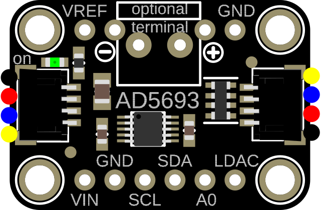
 Design with Adafruit AD5693R Breakout Board in Cirkit Designer
Introduction
The Adafruit AD5693R Breakout Board (Manufacturer Part ID: 5811) is a precision digital-to-analog converter (DAC) designed to provide 16-bit resolution for generating highly accurate analog signals. This component is capable of outputting voltages ranging from 0V to VDD, making it ideal for applications requiring precise voltage control. It features an I2C interface for seamless communication with microcontrollers, enabling easy integration into a variety of projects.
Explore Projects Built with Adafruit AD5693R Breakout Board
 Open Project in Cirkit Designer
 Open Project in Cirkit Designer
 Open Project in Cirkit Designer
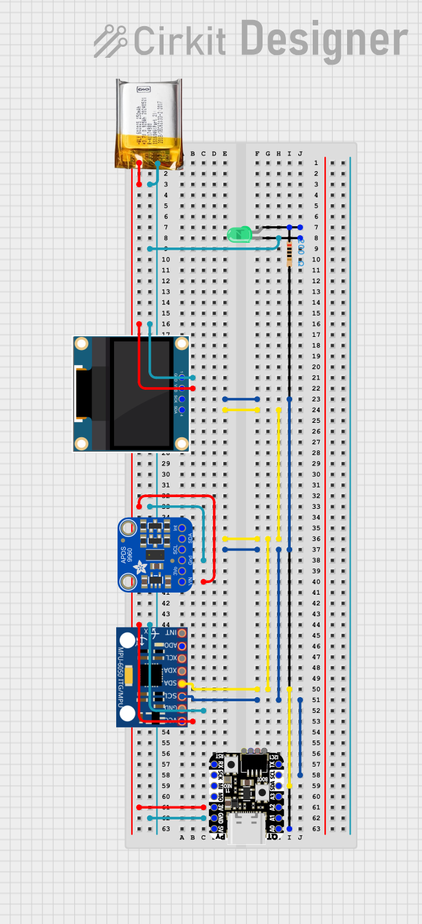 Open Project in Cirkit Designer
Explore Projects Built with Adafruit AD5693R Breakout Board
Open Project in Cirkit DesignerOpen Project in Cirkit DesignerOpen Project in Cirkit DesignerOpen Project in Cirkit DesignerCommon Applications
- Signal generation for testing and calibration
- Precision control of analog devices (e.g., motors, actuators)
- Audio signal processing
- Industrial automation and instrumentation
- Data acquisition systems
Technical Specifications
The Adafruit AD5693R Breakout Board is built around the Analog Devices AD5693R DAC chip. Below are the key technical details:
| Parameter | Specification |
|---|---|
| Resolution | 16-bit |
| Output Voltage Range | 0V to VDD |
| Supply Voltage (VDD) | 2.7V to 5.5V |
| Reference Voltage | Internal 2.5V or external reference |
| Communication Interface | I2C (up to 400 kHz) |
| Power Consumption | 0.7 mW (typical) |
| Operating Temperature Range | -40°C to +125°C |
| Package Type | Breakout board with soldered headers |
Pin Configuration
The breakout board has the following pin layout:
| Pin Name | Description |
|---|---|
| VIN | Power supply input (2.7V to 5.5V) |
| GND | Ground |
| SCL | I2C clock line |
| SDA | I2C data line |
| VOUT | Analog output voltage (0V to VDD) |
| ADR | I2C address selection pin |
| RST | Reset pin (active low) |
Usage Instructions
Connecting the AD5693R to a Microcontroller
- Power Supply: Connect the VIN pin to a 3.3V or 5V power source, and connect the GND pin to the ground of your circuit.
- I2C Communication: Connect the SCL and SDA pins to the corresponding I2C pins on your microcontroller. Use pull-up resistors (typically 4.7kΩ) on the SCL and SDA lines if they are not already present in your circuit.
- Analog Output: The VOUT pin provides the DAC's analog output. Connect this pin to the input of the device or circuit you wish to control.
- I2C Address: Use the ADR pin to configure the I2C address. Leave it floating or connect it to GND/VIN to select the desired address (refer to the datasheet for address options).
- Reset: Optionally, connect the RST pin to a GPIO pin on your microcontroller for manual reset functionality.
Example Arduino Code
Below is an example of how to use the AD5693R with an Arduino UNO to output a specific voltage:
#include <Wire.h>

// I2C address of the AD5693R (default: 0x0C)
#define AD5693R_I2C_ADDRESS 0x0C

void setup() {
  Wire.begin(); // Initialize I2C communication
  Serial.begin(9600); // Initialize serial communication for debugging

  // Set up the DAC
  Serial.println("Initializing AD5693R...");
  setDACOutput(32768); // Set DAC output to mid-scale (50% of full range)
}

void loop() {
  // Example: Sweep the DAC output from 0 to full scale
  for (uint16_t value = 0; value <= 65535; value += 1000) {
    setDACOutput(value);
    delay(10); // Small delay for smooth output
  }
}

// Function to set the DAC output
void setDACOutput(uint16_t value) {
  Wire.beginTransmission(AD5693R_I2C_ADDRESS);
  Wire.write(0x30); // Command to write to DAC register
  Wire.write(value >> 8); // Send the upper 8 bits of the 16-bit value
  Wire.write(value & 0xFF); // Send the lower 8 bits of the 16-bit value
  Wire.endTransmission();

  // Debugging: Print the value being sent to the DAC
  Serial.print("DAC Output Set to: ");
  Serial.println(value);
}
Best Practices
- Use decoupling capacitors (e.g., 0.1µF) near the VIN pin to reduce noise.
- Ensure the I2C pull-up resistors are properly configured for reliable communication.
- Avoid exceeding the maximum voltage ratings to prevent damage to the component.
- Use a stable power supply to maintain accurate output voltages.
Troubleshooting and FAQs
Common Issues
No Output Voltage on VOUT Pin
- Ensure the DAC is powered correctly (check VIN and GND connections).
- Verify the I2C communication is functioning (check SCL and SDA connections).
- Confirm the I2C address matches the configuration of the ADR pin.
Incorrect Output Voltage
- Check the reference voltage source (internal or external) and ensure it is stable.
- Verify the value being sent to the DAC is within the valid range (0 to 65535 for 16-bit resolution).
I2C Communication Errors
- Ensure pull-up resistors are present on the SCL and SDA lines.
- Check for conflicting I2C addresses if multiple devices are on the same bus.
FAQs
Q: Can I use the AD5693R with a 3.3V microcontroller?
A: Yes, the AD5693R supports a supply voltage range of 2.7V to 5.5V, making it compatible with both 3.3V and 5V systems.
Q: How do I select between the internal and external reference voltage?
A: The AD5693R uses an internal 2.5V reference by default. To use an external reference, connect your reference voltage to the appropriate pin (refer to the datasheet for details).
Q: What is the maximum output current of the DAC?
A: The AD5693R is designed for low-current applications and can source/sink up to 10mA. For higher current requirements, use a buffer amplifier.
Q: Can I use the AD5693R for audio applications?
A: Yes, the AD5693R's high resolution and precision make it suitable for audio signal generation and processing.
By following this documentation, you can effectively integrate the Adafruit AD5693R Breakout Board into your projects and achieve precise analog signal control.