How to Use ESP32 WROOM devikit: Examples, Pinouts, and Specs
Introduction
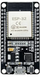
The ESP32 WROOM DevKit, manufactured by Hoysond, is a versatile development board built around the ESP32 chip. It features integrated Wi-Fi and Bluetooth capabilities, making it an excellent choice for Internet of Things (IoT) applications, smart devices, and rapid prototyping. With its powerful dual-core processor, low power consumption, and extensive GPIO options, the ESP32 WROOM DevKit is suitable for a wide range of projects, from home automation to industrial monitoring.
Explore Projects Built with ESP32 WROOM devikit

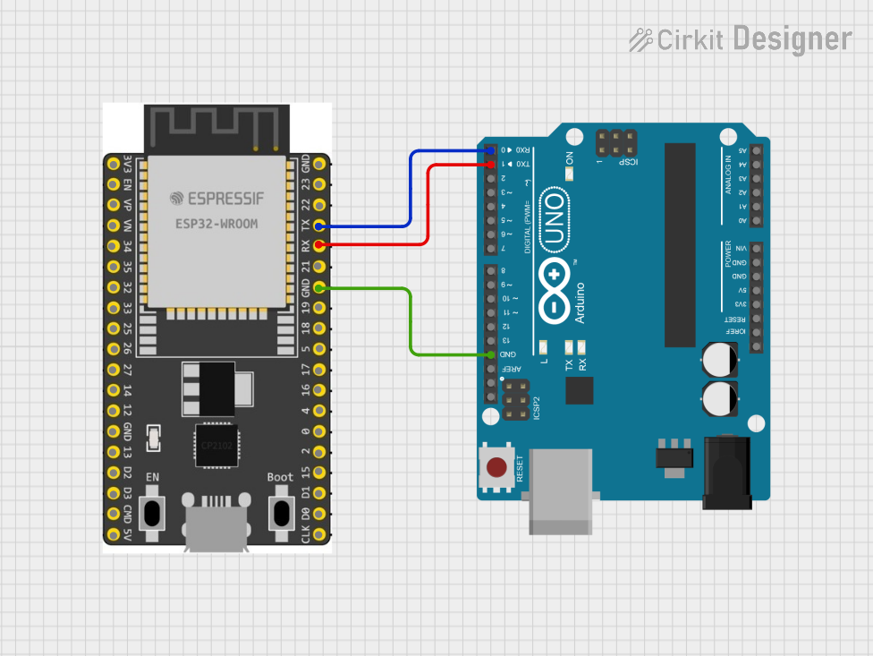

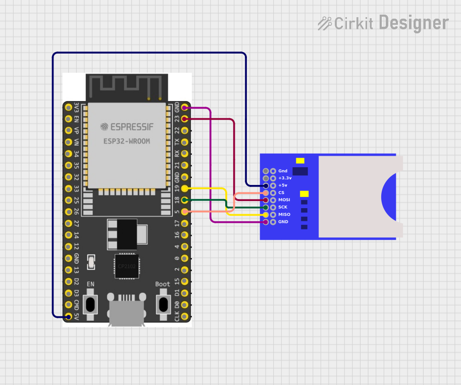
Explore Projects Built with ESP32 WROOM devikit
Common Applications and Use Cases
- IoT devices and smart home systems
- Wireless sensor networks
- Wearable technology
- Robotics and automation
- Prototyping and educational projects
- Bluetooth Low Energy (BLE) applications
Technical Specifications
The ESP32 WROOM DevKit is designed to provide robust performance and flexibility. Below are its key technical details:
Key Technical Details
- Microcontroller: ESP32 dual-core Xtensa LX6 processor
- Clock Speed: Up to 240 MHz
- Flash Memory: 4 MB (varies by model)
- SRAM: 520 KB
- Wireless Connectivity: Wi-Fi 802.11 b/g/n and Bluetooth 4.2 (Classic + BLE)
- Operating Voltage: 3.3V
- Input Voltage (via USB): 5V
- GPIO Pins: 30+ (varies by board version)
- ADC Channels: 18 (12-bit resolution)
- DAC Channels: 2
- PWM Outputs: 16
- Communication Protocols: UART, SPI, I2C, I2S, CAN, and more
- Power Consumption: Ultra-low power modes available
- Dimensions: Approximately 25.5 mm x 51 mm
Pin Configuration and Descriptions
The ESP32 WROOM DevKit features a 38-pin layout. Below is a table summarizing the key pins and their functions:
| Pin Name | Function | Description |
|---|---|---|
| VIN | Power Input | Accepts 5V input from USB or external power supply. |
| GND | Ground | Common ground for the circuit. |
| 3V3 | Power Output | Provides 3.3V output for external components. |
| EN | Enable | Resets the chip when pulled low. |
| IO0 | GPIO0 | Used for boot mode selection; also a general-purpose I/O pin. |
| IO2 | GPIO2 | General-purpose I/O pin; often used for onboard LED. |
| IO12-IO39 | GPIO Pins | General-purpose I/O pins with various functions (PWM, ADC, DAC, etc.). |
| TXD0/RXD0 | UART0 (TX/RX) | Default UART for serial communication. |
| SCL/SDA | I2C Clock/Data | Used for I2C communication. |
| MOSI/MISO | SPI Data (Master Out/In) | Used for SPI communication. |
| A0-A17 | ADC Channels | Analog input pins with 12-bit resolution. |
| DAC1/DAC2 | Digital-to-Analog Converter Channels | Converts digital signals to analog output. |
| BOOT | Boot Mode Selection | Used to enter firmware flashing mode. |
Note: Not all GPIO pins support all functions. Refer to the ESP32 datasheet for detailed pin multiplexing information.
Usage Instructions
The ESP32 WROOM DevKit is easy to use and compatible with popular development environments like Arduino IDE, PlatformIO, and Espressif's ESP-IDF. Below are the steps to get started:
How to Use the Component in a Circuit
- Power the Board: Connect the ESP32 WROOM DevKit to your computer via a micro-USB cable or provide 5V to the VIN pin.
- Install Drivers: Ensure the appropriate USB-to-serial drivers (e.g., CP2102 or CH340) are installed on your computer.
- Set Up Development Environment:
- For Arduino IDE:
- Install the ESP32 board package via the Board Manager.
- Select "ESP32 Dev Module" as the board type.
- For ESP-IDF:
- Follow the official Espressif setup guide to configure the toolchain.
- For Arduino IDE:
- Connect Peripherals: Use jumper wires to connect sensors, actuators, or other components to the GPIO pins.
- Upload Code: Write and upload your code using the development environment of your choice.
Important Considerations and Best Practices
- Voltage Levels: The ESP32 operates at 3.3V logic levels. Avoid connecting 5V signals directly to GPIO pins.
- Boot Mode: To enter bootloader mode for flashing firmware, hold the BOOT button while pressing the EN (reset) button.
- Power Supply: Use a stable power source to avoid unexpected resets or malfunctions.
- Wi-Fi and Bluetooth: Avoid placing the board near metal objects or enclosures that may interfere with wireless signals.
Example Code for Arduino IDE
Below is a simple example to blink an LED connected to GPIO2:
// Blink an LED connected to GPIO2 on the ESP32 WROOM DevKit

#define LED_PIN 2  // GPIO2 is often connected to the onboard LED

void setup() {
  pinMode(LED_PIN, OUTPUT);  // Set GPIO2 as an output pin
}

void loop() {
  digitalWrite(LED_PIN, HIGH);  // Turn the LED on
  delay(1000);                  // Wait for 1 second
  digitalWrite(LED_PIN, LOW);   // Turn the LED off
  delay(1000);                  // Wait for 1 second
}
Troubleshooting and FAQs
Common Issues Users Might Face
- Board Not Detected by Computer:
- Ensure the USB cable is functional and supports data transfer.
- Install the correct USB-to-serial driver (e.g., CP2102 or CH340).
- Code Upload Fails:
- Check the selected board and port in the development environment.
- Hold the BOOT button while uploading the code.
- Wi-Fi Connection Issues:
- Verify the SSID and password in your code.
- Ensure the router is within range and supports 2.4 GHz Wi-Fi.
- Random Resets or Instability:
- Use a stable power supply with sufficient current (at least 500 mA).
- Avoid excessive power draw from GPIO pins.
Solutions and Tips for Troubleshooting
- Debugging Serial Output: Use the Serial Monitor in Arduino IDE or a terminal program to view debug messages.
- Firmware Update: Ensure the ESP32 has the latest firmware to avoid compatibility issues.
- Pin Conflicts: Double-check pin assignments to avoid conflicts with onboard peripherals.
By following this documentation, you can effectively utilize the ESP32 WROOM DevKit for your projects and troubleshoot common issues with ease.